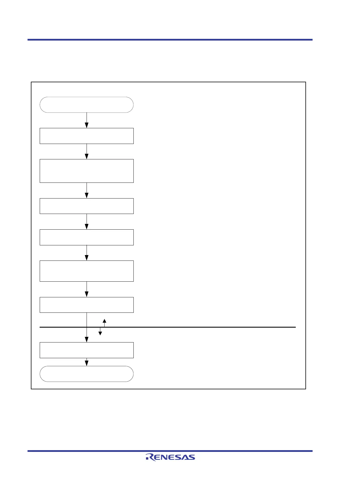
Start
Set the DTCCR.RRS bit to 0
End
Set transfer information
(MRA, MRB, SAR, DAR, CRA, and CRB)
Set the start address of the transfer
information in the DTC vector table
Set the DTCCR.RRS bit to 1
Set the ICU.DTCERn.DTCE bit to 1.
Set the ICU.IERm.IENj bit to 1.
Set the interrupt enable bit for
a request source
[1]
[4]
[5]
[6]
[2]
[3]
Setting for each request
source
Common setting for DTC
Set the DTCST.DTCST bit to 1 [7]
Set the ICU.IERm.IENj bit corresponding to the request source
interrupt to 0 and provide the following settings.
[1] Setting the DTCCR.RRS bit to 0 resets the transfer
information read skip flag. After that, transfer information read
is not skipped during the data transfer. When transfer
information is updated, be sure to make this setting.
[2] Allocate transfer information (MRA, MRB, SAR, DAR, CRA,
and CRB) in the data area. For setting transfer information,
refer to section 19.2, Register Descriptions. For how to
allocate transfer information, refer to section 19.3.1,
Allocating Transfer Information and DTC Vector Table.
[3] Set the start address of the transfer information in the DTC
vector table. For how to set the DTC vector table, refer to
section 19.3.1, Allocating Transfer Information and DTC
Vector Table.
[4] Setting the DTCCR.RRS bit to 1 enables skipping of the
second and the subsequent transfer information read cycles
for continuous data transfer due to the same interrupt source.
The RRS bit can be set to 1 at any time, but this setting
during data transfer becomes valid from the next transfer.
[5] Set the ICU.DTCERn.DTCE bit (n = interrupt vector number)
that corresponds to the DTC request source to 1. Set the
ICU.IERm.IENj bit to 1. For the correspondence between
interrupt sources and DTCERn register, refer to section
15.3.1, Interrupt Vector Table in section 15, Interrupt
Controller (ICUb).
[6] Set the interrupt enable bit of the peripheral module, which is
request source, to 1. When a source interrupt is generated,
the DTC starts operation. For the setting of the interrupt
enable bit, refer to the setting of the peripheral module that is
to be a request source.
[7] Set the DTCST.DTCST bit to 1 (DTC module start)*
1
.
Note 1. The DTCST.DTCST bit can be set even if the setting for
each request source is not completed.

 Loading...


