R01UH0823EJ0100 Rev.1.00 Page 1809 of 1823
Jul 31, 2019
RX23W Group 51. Electrical Characteristics
51.12 Battery Backup Function Characteristics
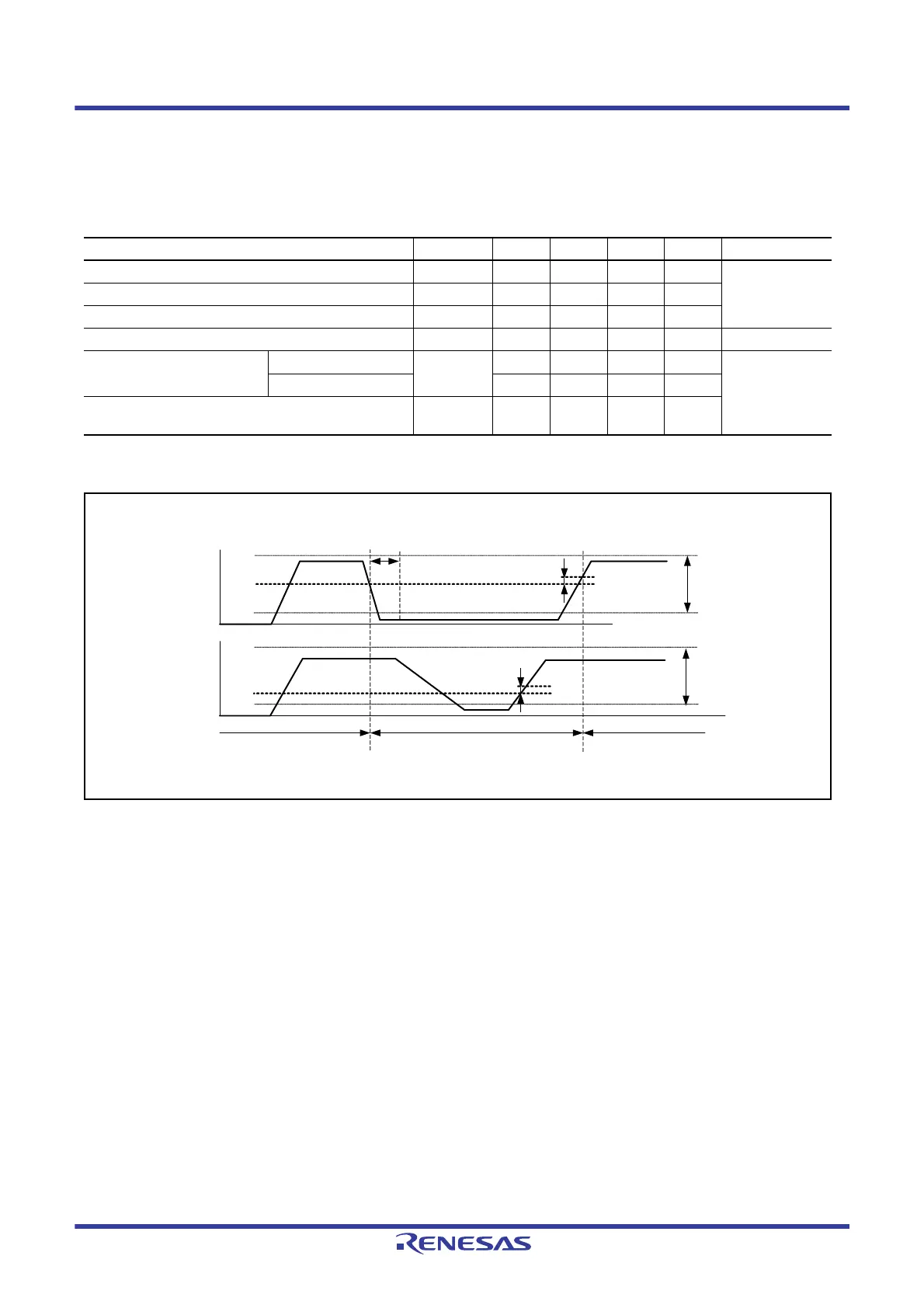
Note: The VCC-off period for starting power supply switching indicates the period in which VCC is below the minimum value of the
voltage level for switching to battery backup (V
DETBATT
).
Figure 51.68 Battery Backup Function Characteristics
Table 51.54 Battery Backup Function Characteristics
Conditions: 1.8 V ≤ VCC = VCC_USB = AVCC0 = VCC_RF = AVCC_RF ≤ 3.6 V, 1.8 V ≤ VBATT ≤ 3.6 V,
VSS = AVSS0 = VREFL0 = VSS_USB = VSS_RF = 0 V, T
a
= –40 to +85°C
Item Symbol Min. Typ. Max. Unit Test Conditions
Voltage level for switching to battery backup (falling) V
DETBATT
1.99 2.09 2.19 V Figure 51.68
Hysteresis width V
VBATTH
—100—mV
VCC-off period for starting power supply switching t
VOFFBATT
— — 350 μs
Allowable voltage change rising/falling gradient dt/dVCC 1.0 — — ms/V Figure 51.7
Level for detection of voltage
drop on the VBATT pin (falling)
VBTLVDLVL[1:0] = 10b V
DETBATLVD
2.11 2.20 2.29 V Figure 51.68
VBTLVDLVL[1:0] = 11b 1.87 2.00 2.13 V
Hysteresis width for detection of voltage drop on the
VBATT pin
V
BATLVDH
—50—mV
VCC
VBATT
Backup power
supply area
VCC supplied
VCC suppliedVBATT supplied
V
DETBATT
VCC voltage
guaranteed
range
VBATT voltage
guaranteed
range
t
VOFFBATT
VCC
Cannot
Be
raised
V
VBATTH
V
DETBATLVD
V
BATLVDH

 Loading...


