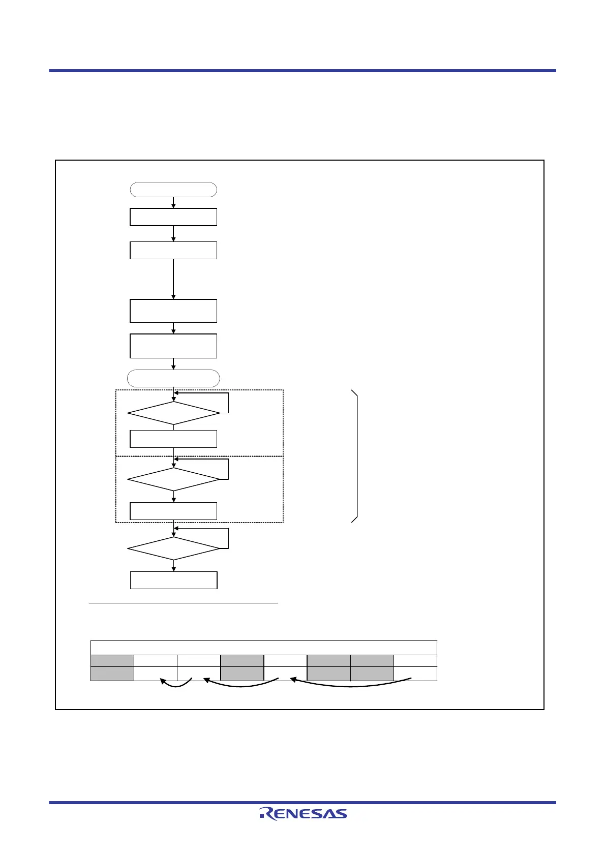
Set interrupt operation
(DTC/ICU)
Set CTSU registers
Set CTSU control
(measurement start)
using CTSUCR0 register
CTSU operation starts
Power supply stabilization
time has elapsed after
CTSUPON = 1
• CTSUWR interrupt operation setting
Transfer from the RAM to the CTSUSSC, CTSUSO0, and CTSUSO1 registers
• CTSURD interrupt operation setting
Transfer the CTSUSC and CTSURC counters to the RAM
Initial setting
CTSUFN generated?
No
Touch determination
processing
Wait for the measurement end interrupt
CTSURD generated?
No
CTSUWR interrupt
generated?
No
Read the measurement result
Set the measurement channel
Transferred by the DTC
when the DTC is set
Transferred by the DTC
when the DTC is set
CTSUSSC register
CTSUSO0 register
CTSUSO1 register
CTSUSC counter
CTSURC counter
Repeat for the number of
the measurement channels
Channel measurement sequence in self-capacitance multi-scan mode
Channel 3
Receive Channels
Channel 2 Channel 1 Channel 0
(1)
(2)
Channel 7 Channel 6 Channel 5 Channel 4
(3)(4)
When a software trigger is used, the CTSUCR0.CTSUSTRT bit is set to 0 when CTSU operation is finished.
CTSUCR0.CTSUSTRT bit: Set this bit to 1
CTSUCR0.CTSUCAP bit: Starting CTSU operation by external trigger can be selected
CTSUCR0.CTSUSNZ bit: Power-saving function during wait state can be enabled or disabled
CTSUCR1 register
• CTSUCR1.CTSUCLK[1:0] bits: Operating clock can be selected
• CTSUCR1.CTSUMD[1:0] bits: Set these bits to 01b
CTSUSDPRS register
• CTSUSDPRS.CTSUSOFF bit: High-pass noise prevention can be turned off
• CTSUSDPRS.CTSUPRMODE[1:0] bits: Set the number of base pulses for synchronous noise prevention
• CTSUSDPRS.CTSUPRRATIO[3:0] bits: Set the measurement time for synchronous noise prevention
CTSUSST register: Set the sensor stabilization time
CTSUCHACn and CTSUCHAC4 registers (n = 0 to 3): Set the enabled channel
Setting
• Select self-capacitance multi-scan mode (CTSUCR1.CTSUMD[1:0] bits = 01b)
• Set channels 0, 3, 5, and 6 to enabled channels (CTSUCHACn.CTSUCHACn[7:0] bits (n = 0 to 3) = 01101001b)

 Loading...


