R01UH0823EJ0100 Rev.1.00 Page 833 of 1823
Jul 31, 2019
RX23W Group 30. Watchdog Timer (WDTA)
30.3.6 Reading the Down-Counter Value
The WDT stores the counter value in the WDTSR.CNTVAL[13:0] bits. Thus, the counter value can be checked through
the WDTSR.CNTVAL[13:0] bits.
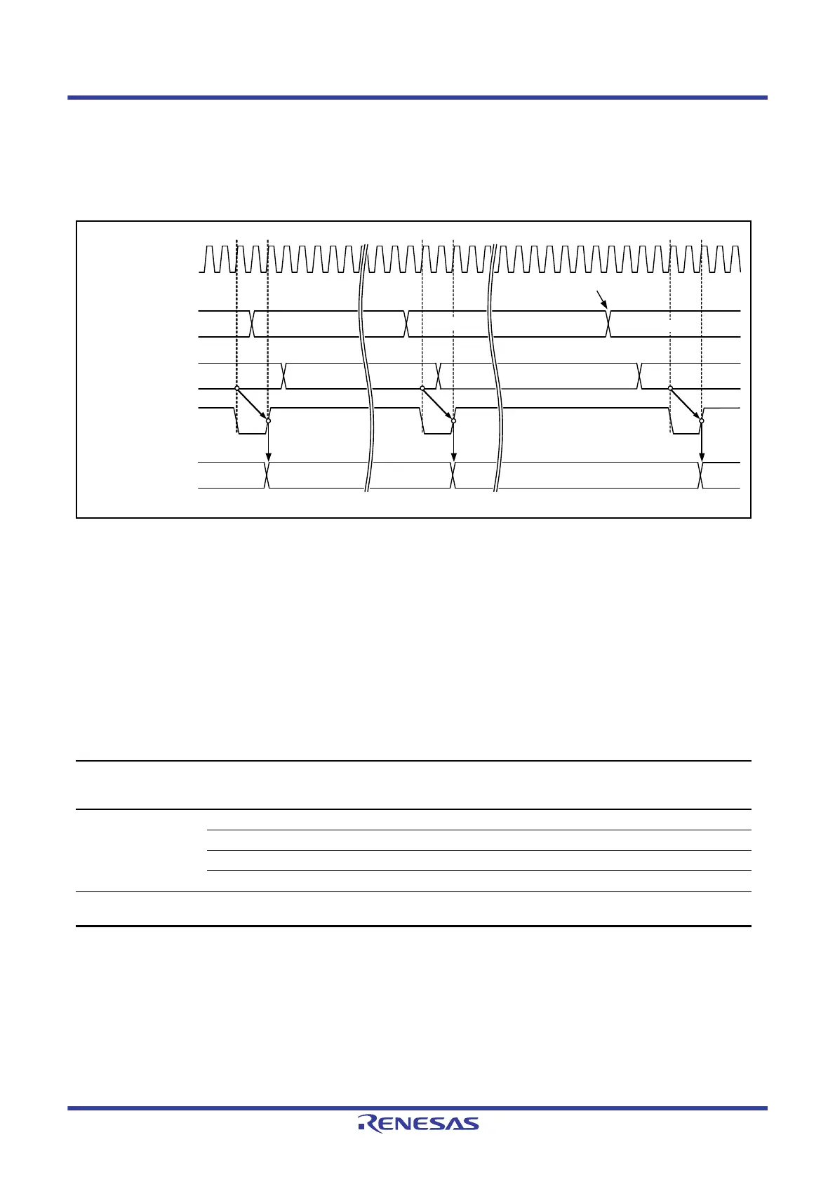
Figure 30.7 shows the processing for reading the WDT down-counter value when the clock division ratio = PCLK/64.
Figure 30.7 Processing for Reading WDT Down-Counter Value
(WDTCR.CKS[3:0] = 0100b, WDTCR.TOPS[1:0] = 01b)
30.3.7 Correspondence between Option Function Select Register 0 (OFS0) and WDT
Registers
Table 30.5 lists the correspondence between option function select register 0 (OFS0) used in auto-start mode and the
registers used in register start mode.
Do not change the OFS0 register setting during WDT operation.
For details on the OFS0 register, refer to
section 7.2.1, Option Function Select Register 0 (OFS0).
Table 30.5 Correspondence between Option Function Select Register 0 (OFS0) and WDT Registers
Target of Control Function
OFS0 Register
(Enabled in Auto-Start Mode)
OFS0.WDTSTRT = 0
WDT Registers
(Enabled in Register Start Mode)
OFS0.WDTSTRT = 1
Down-counter Timeout period selection OFS0.WDTTOPS[1:0] WDTCR.TOPS[1:0]
Clock division ratio selection OFS0.WDTCKS[3:0] WDTCR.CKS[3:0]
Window start position selection OFS0.WDTRPSS[1:0] WDTCR.RPSS[1:0]
Window end position selection OFS0.WDTRPES[1:0] WDTCR.RPES[1:0]
Reset output or interrupt
request output
Reset output or interrupt request
output selection
OFS0.WDTRSTIRQS WDTRCR.RSTIRQS
(n)h
Peripheral module clock
(PCLK)
WDTSR.CNTVAL
[13:0] read signal
(internal signal)
Bits WDTSR.CNTVAL
[13:0]
Counter value
Refreshing
0FFFh(n+1)h (n-1)h
(n+1)h
(n)h
(n-1)h
(n-1)h
WDTSR.CNTVAL
[13:0] read data
xxxxh (n+1)h (n)h 0FFFh
(n)h
(n-1)h
0FFFh

 Loading...


