R01UH0823EJ0100 Rev.1.00 Page 1449 of 1823
Jul 31, 2019
RX23W Group 40. SD Host Interface (SDHIa)
40.3.3 SD Card Detection
The SDHI can detect an SD card using either the SDHI_CD pin or SDHI_D3 pin.
40.3.3.1 Using the SDHI_CD Pin to Detect an SD Card
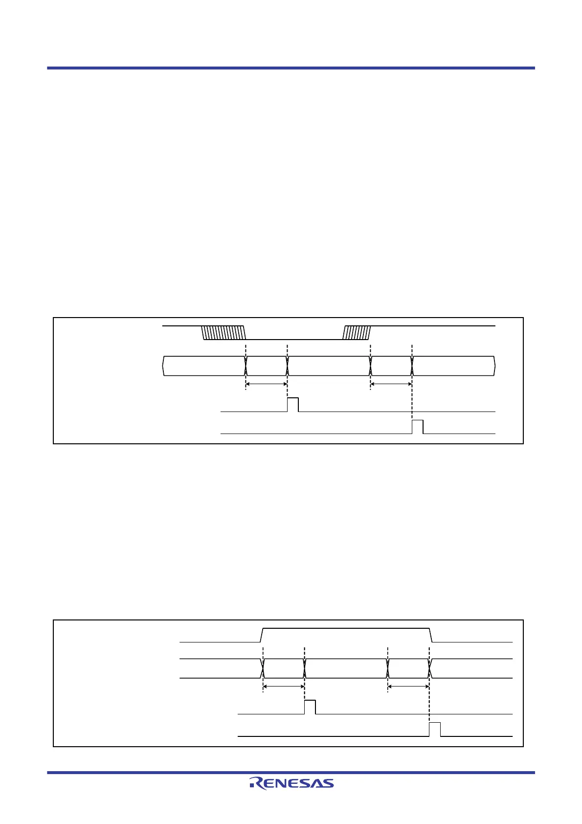
Figure 40.6 shows the timing chart for SD card detection using the SDHI_CD pin. The SDHI_CD pin is connected to
the card detection switch of the SD card connector, and is pulled-up by the MCU. The pull-up resistance value is
determined by the specifications of the host device. Note that there are some SD card sockets whose card detection
switches become open when the SD card is inserted.
Detecting SD card insertion
The signal from the SDHI_CD pin becomes low when an SD card is inserted. This causes the SDSTS1.SDCDIN
flag to become 1 if the SDHI_CD pin is low for the number of cycles set in the SDOPT.CTOP[3:0] bits. The
SDSTS1.SDCDIN flag is cleared by setting it to 0.
Detecting SD card removal
The signal from the SDHI_CD pin becomes high when the SD card is removed. This causes the SDSTS1.SDCDRM
flag to become 1 if the SDHI_CD pin is high for the number of cycles set in the SDOPT.CTOP[3:0] bits. The
SDSTS1.SDCDRM flag is cleared by setting it to 0.
Figure 40.6 SD Card Detection Using the SDHI_CD Pin
40.3.3.2 Using the SDHI_D3 Pin to Detect an SD Card
Figure 40.7 shows the timing chart for SD card detection using the SDHI_D3 pin. The SDHI_D3 pin is pulled-down by
the MCU. The pull-down resistance value is determined by the specifications of the host device.
Detecting SD card insertion
The signal from the SDHI_D3 pin becomes high when an SD card is inserted. This causes the SDSTS1.SDD3IN
flag to become 1. The SDSTS1.SDD3IN flag is cleared by setting it to 0.
Detecting SD card removal
The signal from the SDHI_D3 pin becomes low when the SD card is removed. This causes the SDSTS1.SDD3RM
flag to become 1. The SDSTS1.SDD3RM flag is cleared by setting it to 0.
Figure 40.7 SD Card Detection Using the SDHI_D3 Pin
No SD card
SD card
detected
SD card ready
SD card
detected
No SD card
SDSTS1.SDCDIN flag (SD card
insertion detected by the SDHI_CD pin)
Cleared
Cleared
SDHI_CD pin
CTOP[3:0]
bit value
CTOP[3:0]
bit value
SDSTS1.SDCDRM flag (SD card
removal detected by the SDHI_CD pin)
Card
detected
Card ready
Card
detected
Cleared
Cleared
SDHI_D3 pin
2 × PCLKB
SDSTS1.SDD3IN flag
(SD card insertion detected by the SDHI_D3 pin)
SDSTS1.SDD3RM flag
(SD card removal detected by the SDHI_D3 pin)
2 × PCLKB
No card No card

 Loading...


