EasyManuals Logo

Renesas RX Series User Manual

Renesas RX Series
1823 pages
To Next Page IconTo Next Page
To Previous Page IconTo Previous Page
Page #1101 background imageLoading...
Page #1101 background image
R01UH0823EJ0100 Rev.1.00 Page 1101 of 1823
Jul 31, 2019
RX23W Group 33. Serial Communications Interface (SCIg, SCIh)
Figure 33.77 Example of Flowchart for Transition to Software Standby Mode during Transmission
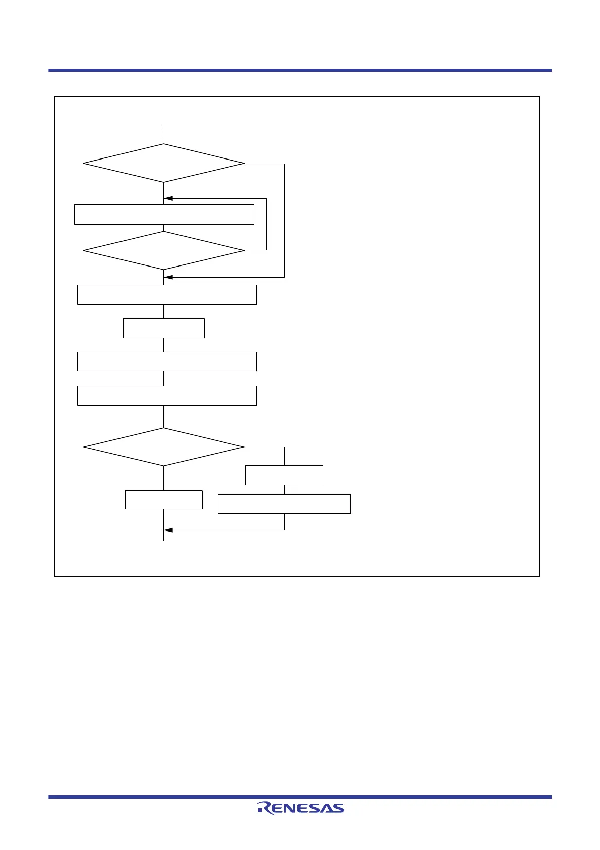
Start data transmission
Initialization
SCR.TE = 1
SCR.TE bit = 0
Make transition to software standby mode
Cancel software standby mode
No
No
No
Yes
Yes
Yes
All data transmitted?
SSR.TEND = 1
Change operating mode?
Data transmission
[ 1 ]
[ 4 ]
Read TEND flag in SSR
Make the I/O port function settings
[ 2 ]
[ 3 ]
[ 1 ] Data being transmitted is lost halfway. Data can be
normally transmitted from the CPU by setting the
TE bit in SCR to 1, reading SSR, and writing data to
TDR after canceling software standby mode.
However, if the DMAC or DTC has been activated,
the data remaining in the DMAC or DTC will be
transmitted when both the TE and TIE bits in SCR
are set to 1.
[ 2 ] Make the I/O port function settings to switch the
TXDn pin to operate as a general I/O port.
[ 3 ] Set the TIE and TEIE bits in the SCR if they are
currently set to 1.
[ 4 ] This includes the setting for the module stop state.

Table of Contents

Questions and Answers:

Question and Answer IconNeed help?

Do you have a question about the Renesas RX Series and is the answer not in the manual?

Renesas RX Series Specifications

General IconGeneral
CoreRXv1, RXv2, RXv3
Flash MemoryUp to 8 MB
RAMUp to 1 MB
Operating Voltage1.62V to 5.5V
Operating Temperature-40°C to +85°C or +105°C
PackageBGA, LQFP
ADC Resolution12-bit
DAC Resolution12-bit
Communication InterfacesSCI, SPI, I2C, USB, Ethernet, CAN
Architecture32-bit
Security FeaturesMemory Protection Unit (MPU)

Related product manuals