R01UH0823EJ0100 Rev.1.00 Page 1406 of 1823
Jul 31, 2019
RX23W Group 38. Serial Peripheral Interface (RSPIa)
(3) Initialization Flowchart
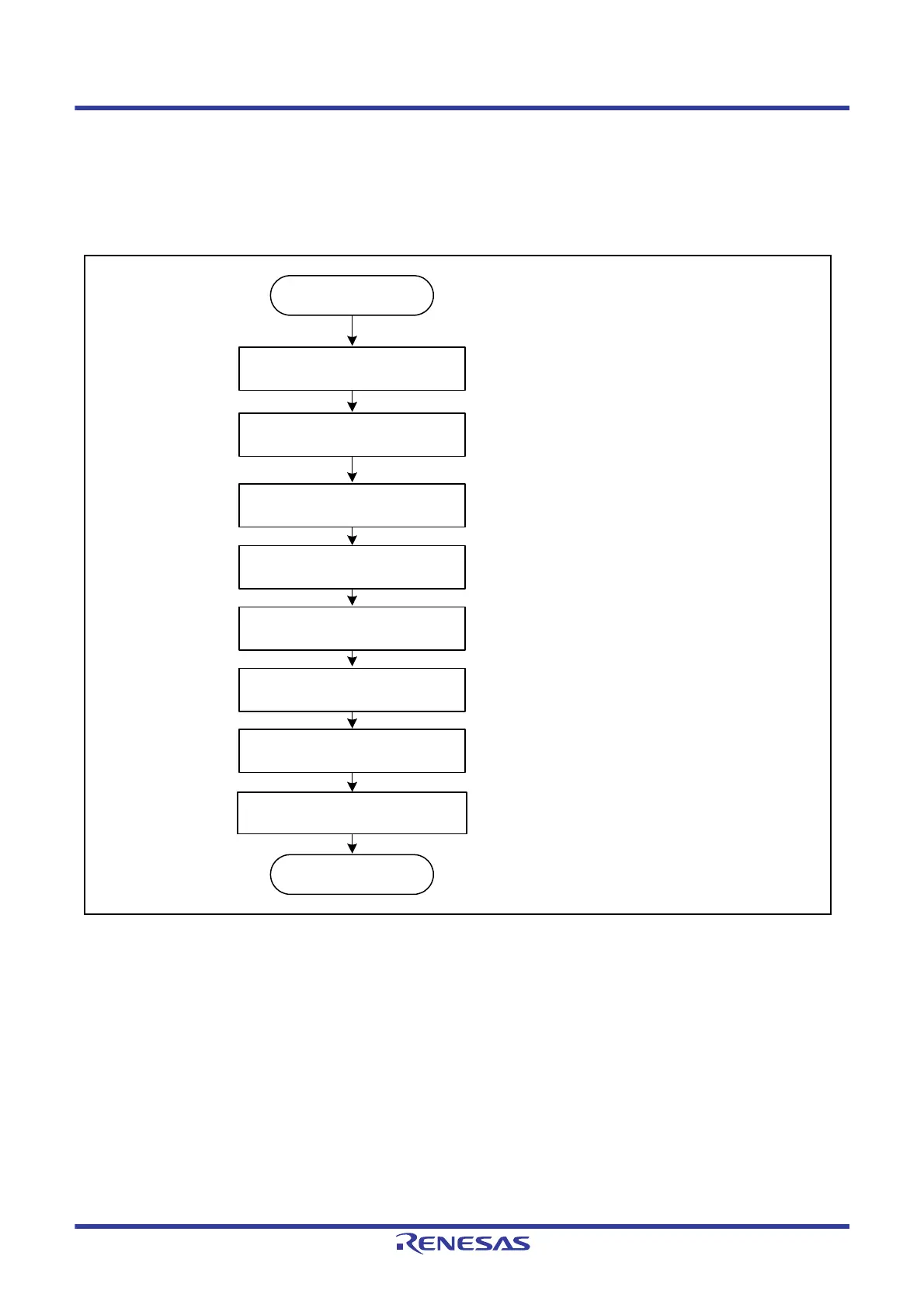
Figure 38.47 is a flowchart illustrating an example of initialization in clock synchronous operation when the RSPI is
used in slave mode. For a description of how to set up the interrupt controller, DMAC, and I/O ports, refer to the
descriptions given in the individual blocks.
Figure 38.47 Example of Initialization Flowchart in Slave Mode (Clock Synchronous Operation)
(4) Flow of Software Processing
Software processing during clock-synchronous slave operation is the same as that for SPI slave operation. For details,
refer to
section 38.3.10.2, (6) Software Processing Flow. Note that mode fault errors will not occur.
Set RSPI data control
register (SPDCR)
Set RSPI command register 0
(SPCMD0)
Set I/O ports
Set RSPI control register
(SPCR)
Set interrupt controller
Set DMAC
• Sets number of frames to be used.
(when using an interrupt)
(when using the DMAC)
• Sets MSB or LSB first.
• Sets data length.
• Sets clock phase.
• Sets clock polarity.
• Sets slave mode.
• Sets interrupt mask.
• Sets RSPI mode.
Set RSPI control register 2 (SPCR2)
• Sets parity function.
• Sets interrupt mask.
Read RSPI control register (SPCR)
Start of initialization in
slave mode
End of initialization in
slave mode

 Loading...


