January 2007
4-240
WorkCentre 7132
ADJ 9.1.1
Reversion 4.0
Repairs/Adjustments
2. Disconnect the Network cable from the machine.
3. Enter UI Diagnostic Mode.
4. Set the following NVM’s in Table 1, to the following default values.
Tray 1 Lead Edge Set Up
Adjustment
NOTE: To properly view printed image, remove from center output tray and Flip Left to Right.
1. Enter UI Diagnostic Mode.
2. Select the Print Test Pattern routine and enter 58.
NOTE: Ensure Tray 1 is loaded with 11x17 or A3 paper and Tray 1 is selected. The
default tray is Tray 1.
3. Press the Start button.
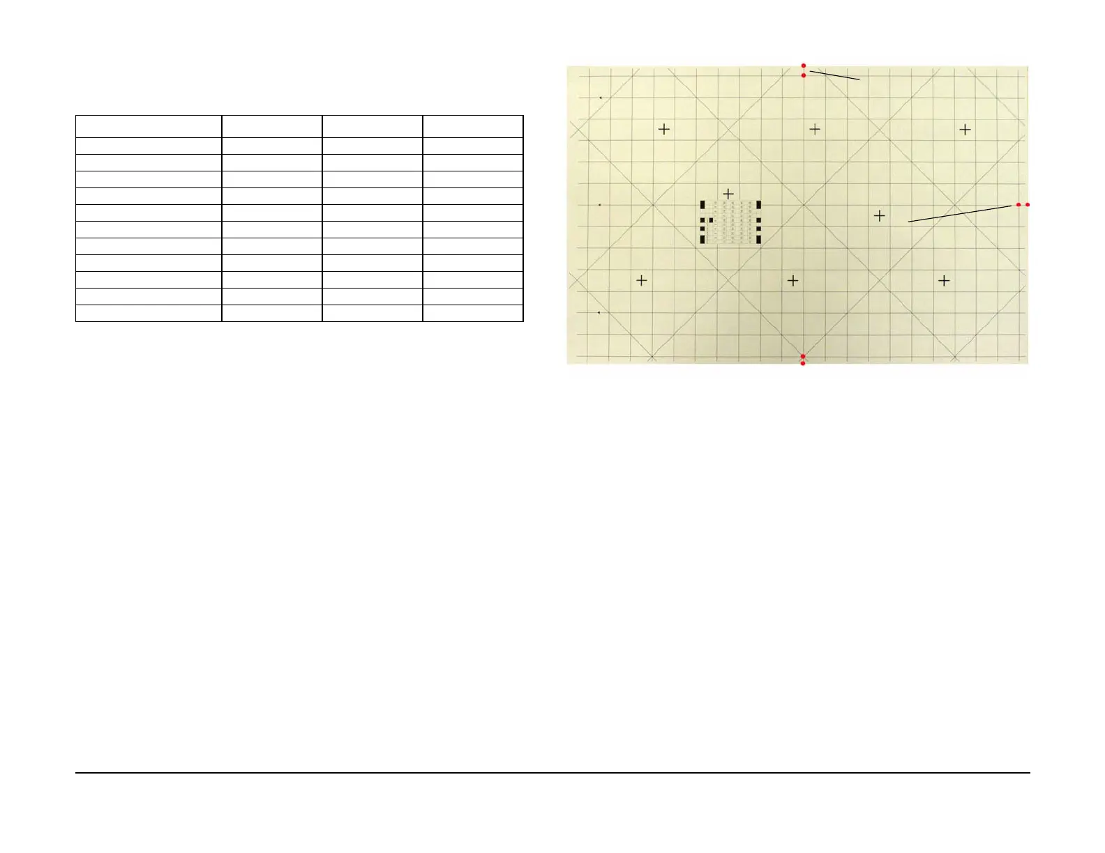
4. Remove the copy from the center exit tray and position it as shown in Figure 1.
NOTE: The Trail Edge of the image is being measured to the Trail Edge of the paper and
the entire image is shifted by any adjustments.
5. Refer to Figure 1. Measure and record the dimensions.
Figure 1 Measurement on Test Pattern #58
6. Determine the direction and the amount the image must be moved to achieve the 10.0 +/-
0.5mm dimension.
NOTE: 9 bits = 1 mm
7. Enter NVM Read/Write and enter 742-031, select Confirm/Change.
8. Enter the new NVM value into Current Value, and press the Start button.
9. Enter Print Test Pattern and enter number 58, press the Start button.
10. Repeat steps 6 through 9 until the correct Lead Edge measurement is achieved.
Lead Edge Adjustment Duplex
Adjustment
1. Ensure Tray 1 is loaded with 11x17” or A3 paper, Tray 1 and Duplex is selected. The
default tray is Tray 1.
NOTE: The default is Tray 1.
2. Ensure that ADJ 11.1.1, IIT Lead Edge/Side Edge Registration has been performed.
NOTE: Use the Test Pattern Original that was created in ADJ 11.1.1, IIT Lead Edge/Side
Edge Registration or create a Test Pattern Original in the next step.
3. To create a test pattern original, use a plain white sheet of 11x17” paper and fold the sheet
precisely in half lengthwise and width wise. Then with a straight edge, draw a straight line
in the length wise crease and a straight line in the width wise edge. Write the words “Lead
Edge” on the short edge that will be placed on the platen glass registration edge. (Figure
2)
Table 1 Default NVM Settings
Description NVM Default Values Range
Lead Edge ALL 742-031 66 0 to 160
L/E Tray 1 - 3 742-039 80 0 to 160
L/E MSI 742-032 80 0 to 160
L/E Duplex 742-046 80 0 to 255
Side Edge Tray 1 742-002 0 -25 to 25
S/E MSI 742-009 0 -25 to 25
S/E Tray 2 742-022 3 -25 to 25
S/E Tray 3 742-023 0 -25 to 25
S/E Duplex Tray 1 742-018 0 -25 to 25
S/E Duplex Tray 2 742-019 0 -25 to 25
S/E Duplex Tray 3 742-020 0 -25 to 25
Measurement points
for paper Edge = 10.0
+/- 0.5 mm
Measurement points
for Side Edge = 10.0
+/- 0.5 mm

 Loading...


