January 2007
4-242
WorkCentre 7132
ADJ 9.1.1, ADJ 9.1.2
Reversion 4.0
Repairs/Adjustments
3. Select Paper Tray 1.
4. Select the Print Count and press the Start button.
5. The Side Edge Registration dimensions should be 10.0 +/- 0.5mm. See Figure 1.
6. Determine the difference between the measured dimensions and the desired specifica-
tions.
7. Calculate the number of NVM bits and the direction of movement.
NOTE: Side Edge Registration. Increase the value to move the image toward the side
edge of the paper. (Each bit = approximately .2mm).
8. Enter NVM Read/Write and enter the NVM location for Side Edge Tray 1 (742-002) from
Table 1.
9. Select Confirm/Change, and change the Current Value with the NVM bits determined.
10. Select Confirm.
11. Enter Print Test Pattern and print test pattern #58.
12. Select Paper Tray 1.
13. Select the Print Count and press the Start button.
14. Repeat steps 5 through 14 to achieve the 10.0 +/- 0.5mm dimension for the Side Edge.
15. Repeat steps 5 through 14 for Trays 2, and 3.
16. When using 11x17” paper in the MSI and selecting LEF, change NVM location 870-211 to
24.
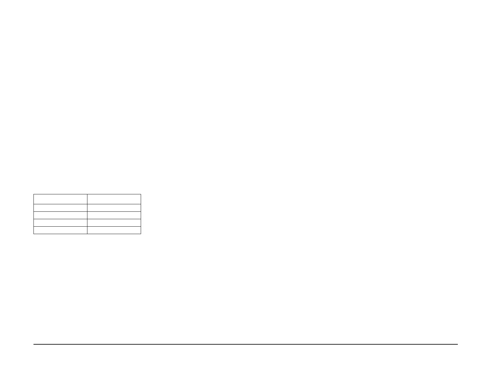
17. Use Table 2 if using other size paper in the MSI for this procedure:
NOTE: When the machine powers off then powers on, the NVM location 870-211 will
return to setting 5 for A4 paper.
18. Exit Diagnostics.
ADJ 9.1.2 Max Setup
Purpose
To conduct a check of the machine and set it up so that excellent copy quality can be consis-
tently obtained by stabilizing the development potential and copy density.
Adjustment
Max Setup consists of several separate adjustments that should be performed in the following
sequence:
1. IIT Calibration ADJ 9.1.8
2. Procon On/Off Print ADJ 9.1.10
3. Adjust Toner Density ADJ 9.1.0
4. TRC Adjustment ADJ 9.1.6
Table 2 NVM location 870-211
Paper Size Set NVM to:
A4 LEF 5
A3 LEF 6
8.5 x 11 LEF 19
11 x 17 LEF 24

 Loading...


