January 2007
4-255
WorkCentre 7132
ADJ 9.2.1, ADJ 9.3.1
Repairs/Adjustments
Reversion 4.0
ADJ 9.2.1 Edge Erase Value Adjustment
Purpose
To correct the Lead, Tail Edge and both Side Edge (rear/front) erase values.
NOTE: The IOT Lead Edge/Side Edge Registration must be adjusted.
Check
1. Enter UI Diagnostic Mode.
2. Select NVM Read/Write.
3. Set Chain-Link No. 780-066 (Image Area) to 0.
4. Specify a tray with paper. Make a black copy with the Platen Cover open.
5. Check that the white sections of the Lead, Tail and Side Edges are 2mm.
Adjustment
1. Enter UI Diagnostic Mode.
2. Select NVM Read/Write.
3. Adjust the measured values using the following NVM so that the measured values fall
within the specifications (2mm).
If the setting value is increased, the erase value increases.
NOTE: A value of 10 moves the image 1mm.
4. After adjustment, make another black copy without using any originals and leaving the
Platen Cover open.
5. Repeat the procedure until the measured values of the Lead (A), and Side (B) Edges fall
within the specifications.
ADJ 9.3.1 Software Loading and Upgrading
Purpose
The purpose of this procedure is to enable updating the machine software (ESS, FAX, IISS,
and IOT) or when reinstallation of the software is required due to a failure. The PWS Diagnos
-
tic tool will be used for this procedure.
CAUTION
This procedure is generic in nature and is intended as an overview only. Always follow the
instructions that come with the software. There may be additional steps added, or other spe
-
cial requirements that vary from version to version.
Setting up the PWS
1. Using the instructions on the pull out sheet that comes with the system software disc, load
the WC 7132 software download tool on you PWS.
2. Make a copy of the color test pattern 82E13120 and check for Image Quality problems.
Resolve any problems before performing the software loading.
3. Print a copy of the Systems Settings List.
4. Switch off the WC 7132.
5. Disconnect the RJ45 Network Connector to the customer’s network.
6. Connect the PWS to the USB 1.1 port on the WC 7132.
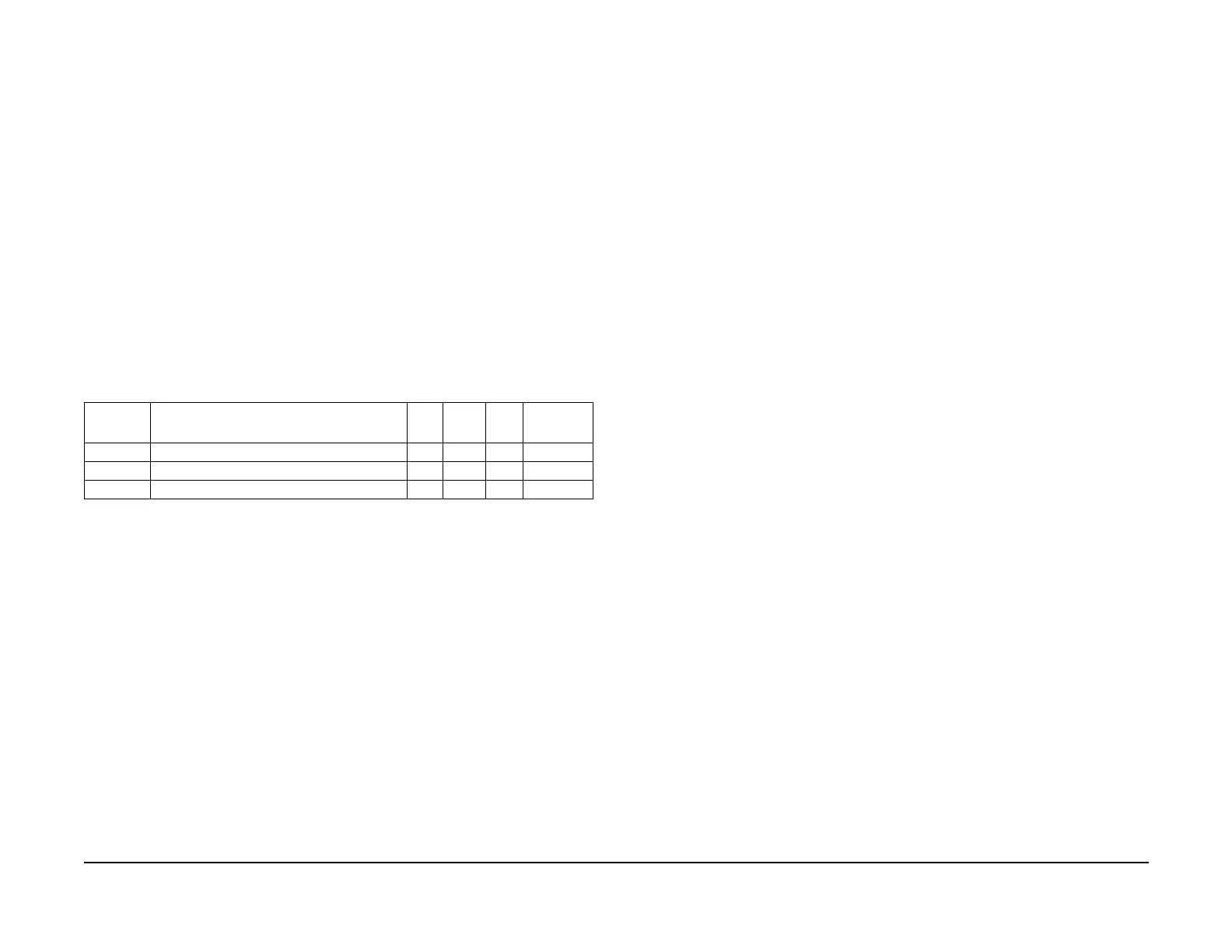
Table 1 NVM List
Chain
Link
Name Min. Initial Max Increment
780-066 LEAD EDGE ERASE ADJUSTMENT 40 40 50 1mm
780-067 TRAIL EDGE ERASE ADJUSTMENT 20 20 30 1mm
780-068 SIDE EDGE ERASE ADJUSTMENT 10 20 30 1mm

 Loading...


