January 2007
6-161
WorkCentre 7132
Controller & Fax NVM List
General procedures information
Reversion 4.0
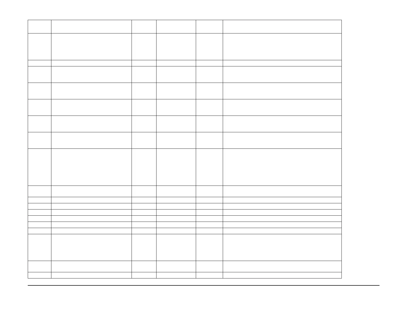
825-257 Channel 0 G3 TSI/CIG Send TSI: Notifica-
tion signal of the Sender ID by the signal
for the CSI signal from the recipient. CIG:
Indicates recognition information of the call
station.
0~255 0: Auto Read/Write 0~255, 0: Auto, 1: Forced transmit, 10: Not transmit
825-263 G3 TX Cable Equalizer for Channel 0 0~3 1: 4dB Read/Write 0: 0dB, 1: 4dB, 2: 8dB, 3: 12dB
825-264 Implications of G3 TX Cable Equalizer for
Channel 1 are different depending on
machine model and configuration
0~3 1: 4dB Read/Write 0: 0dB, 1: 4dB, 2: 8dB, 3: 12dB
825-265 Implications of G3 TX Cable Equalizer for
Channel 2 are different depending on
machine model and configuration
0~3 1: 4dB Read/Write 0: 0dB, 1: 4dB, 2: 8dB, 3: 12dB
825-266 Implications of G3 TX Cable Equalizer for
Channel 3 are different depending on
machine model and configuration
0~3 1: 4dB Read/Write 0: 0dB, 1: 4dB, 2: 8dB, 3: 12dB
825-267 Implications of G3 TX Cable Equalizer for
Channel 4 are different depending on
machine model and configuration
0~3 1: 4dB Read/Write 0: 0dB, 1: 4dB, 2: 8dB, 3: 12dB
825-268 Implications of G3 TX Cable Equalizer for
Channel 5 are different depending on
machine model and configuration
0~3 1: 4dB Read/Write 0: 0dB, 1: 4dB, 2: 8dB, 3: 12dB
825-274 Error line ends in error when it reaches the
specified value. When errors [No. of Lines],
error line will send RTN when 1/2 or more
of the specified value is reached. Sends
RTP when 1/4 or more of the specified
value is reached. Sends MCF when less
than 1/4 of the specified value is reached.
0~5 0: No limit Read/Write 0: No limit, 1: 128line, 2: 256line, 3: 512line, 4: 1024line, 5:
2048line
825-275 Selection of error determination reference
when RTN is sent.
0~1 0: Proportion Read/Write 0: Proportion, 1: No. of lines
825-276 Tone Incoming Detection Level for Ch0 0~3 1: -43dBm Read/Write 0: -48dBm, 1: -43dBm, 2: -38dBm, 3: -33dBm
825-277 Tone Incoming Detection Level for Ch1 0~3 1: -43dBm Read/Write 0: -48dBm, 1: -43dBm, 2: -38dBm, 3: -33dBm
825-278 Tone Incoming Detection Level for Ch2 0~3 1: -43dBm Read/Write 0: -48dBm, 1: -43dBm, 2: -38dBm, 3: -33dBm
825-279 Tone Incoming Detection Level for Ch3 0~3 1: -43dBm Read/Write 0: -48dBm, 1: -43dBm, 2: -38dBm, 3: -33dBm
825-280 Tone Incoming Detection Level for Ch4 0~3 1: -43dBm Read/Write 0: -48dBm, 1: -43dBm, 2: -38dBm, 3: -33dBm
825-281 Tone Incoming Detection Level for Ch5 0~3 1: -43dBm Read/Write 0: -48dBm, 1: -43dBm, 2: -38dBm, 3: -33dBm
825-285 Communication declaration paper size 0x0000~0x0
200
0x014c 0726: A3,
A4, B4, A4LEF,
A5LEF, B5LEF, Let
-
ter, Legal, Ledger,
Letter LEF
Read/Write 0x0000 0002: A3, 0x0000 0004: A4, 0x0000 0020: B4, 0x0000
0100: Letter, 0x0000 0200: Legal, 0x0000 0400: Ledger, 0x0000
0800: 8.5x13 inch, 0x0004 0000: A4LEF, 0x0008 0000: A5LEF,
0x0040 0000: B5LEF, 0x0100 0000: Letter LEF, 0x0200 0000:
Letter Half LEF
825-322 Set the enabling/disabling of the capability
regarding the V34 modulation method.
0~1 1: Enable Read/Write 0: Disable, 1: Enable
825-421 CED Send Start Time 0~3 2: 1.0sec Read/Write 0: 2.0sec, 1: 0.2sec, 2: 1.0sec, 3: 2.3sec
Table 11 NVM 825 FAX Service
Chain-Link NVM Name
Setup
Range Initial Value Read/Write Description
 Loading...


