January 2007
4-34
WorkCentre 7132
REP 4.2.2, REP 4.2.3
Reversion 4.0
Repairs/Adjustments
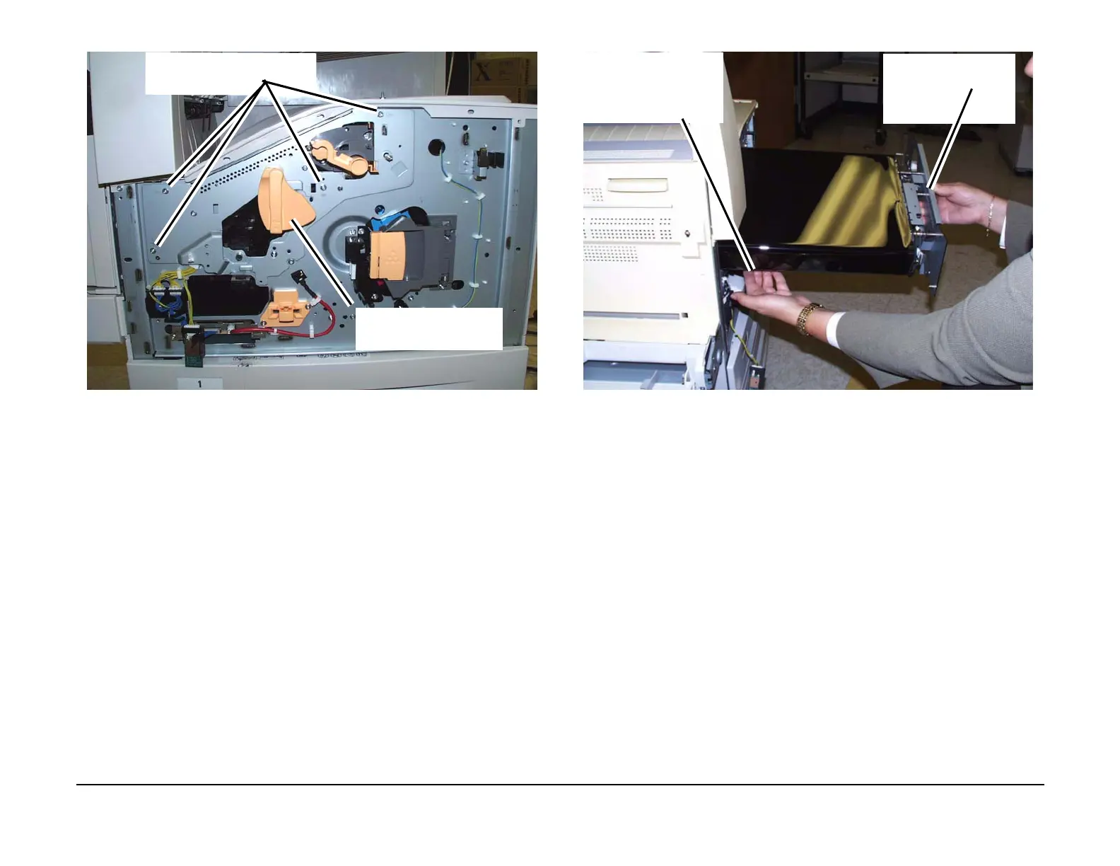
Figure 8 Preparing to removing the IBT Module
CAUTION
Do not touch the surface of the IBT Belt with hands. Print quality can be affected by belt sur-
face residue and marks.
13. Pull the IBT Module out of the machine. (Figure 9)
Figure 9 Removing the IBT Module from the machine
14. Place the IBT Module on a clean work surface.
NOTE: If the IBT Belt is to be removed, proceed to the IBT Belt procedure. (REP 4.2.5)
Replacement
1. Rotate the couplings to fully extent the two BTR2 levers.
2. With the two BTR2 levers fully extend, manually position them behind the IBT Module
frame. This will allow the IBT Module to be inserted into the opening in the machine.
3. When the IBT Module is in the machine, then move the two BTR2 levers away from the
IBT Module frame. This will allow the levers to capture the BTR2 when the left side door is
closed.
4. Install the IBT Module in reverse order of removal.
Remove the screws (4)
1
Remove the Tension Handle
upport the inboard end of
he IBT Module by han-
ling the metal cross bar
nder the Module.
Pull the IBT Module
from the machine

 Loading...


