Programming Examples
13-16 ADSP-21368 SHARC Processor Hardware Reference
For more information, see “Power Management Control Register
(PMCTL)” on page A-170. The equation and procedure for programming
a master clock input is:
1. Set the core clock rate using the values below.
PLLM/PLLN = CCLK
where M = 29, N = 4 for a
CCLK of 241.64 MHz
2. Divide
CCLK rate by 2 (fixed) to provide a PCLK (peripheral clock)
rate of 120.82 MHz.
3. PCLK is divided by 4 (fixed) to provide the PCG_CLKx_O rate of
30.21 MHz for each of the SRCs.
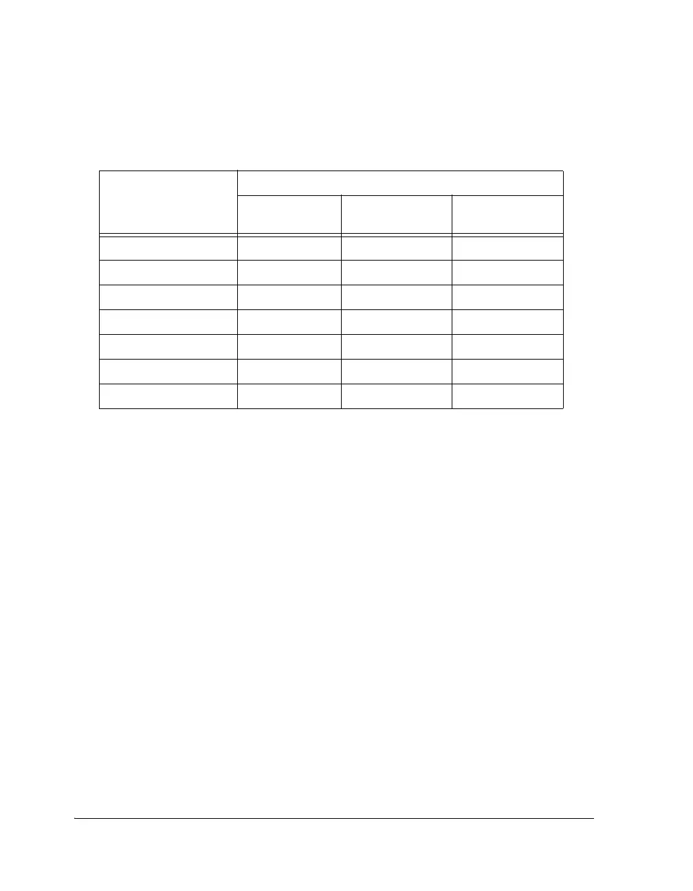
Table 13-2. Precision Clock Generator Division Ratios
(33.330 CLKIN)
Sample Rate kHz)
PCG Divisors
PCG CLOCK
INPUT
SCLK FSYNC
1
130.195 1 4 256
65.098 2 8 512
43.398 3 12 768
32.549 4 16 1024
26.039 5 20 1280
21.699 6 24 1536
18.599 7 28 1792
1 The frame sync divisor should be an even integer in order to produce a 50% duty cycle
waveform. See “Frame Sync Outputs” on page 13-4.
 Loading...


