Power Management Control Register (PMCTL)
A-172 ADSP-21368 SHARC Processor Hardware Reference
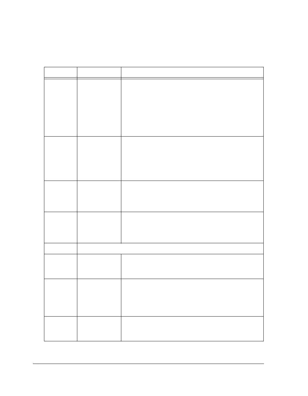
Table A-70. PMCTL Register Bit Descriptions
Bit Name Description
5–0 PLLM PLL Multiplier (read/write).
PLLM = 0 PLL multiplier = 64
0<PLLM<63 PLL multiplier = PLLM
CLK_CFG1–0 reset value
00 = 0000110
01 = 100000
10 = 010000
11 = 000110
7–6 PLLDx PLL Divider (read/write).
00 = CK divider = 1
01 = CK divider = 2
10 = CK divider = 4
11 = CK divider = 8
CLK_CFG1–0 reset value x x 00
8INDIVInput Divisor (read/write).
0 = divide by 1
1 = divide by 2
Reset Value = 0
9DIVENEnable PLL Divider Value Loading (read/write).
0 = Do not load PLLDx
1 = Load PLLDx
Reset value = 0
10 Reserved
11 SP67OFF Serial Port 6, 7 Clock Enable.
0 = SPORT 6, 7 in normal mode
1 = Shut down clock to SPORT 6, 7
12 CLKOUTEN Clockout Enable.
Mux select for CLKOUT and RESETOUT
0 = Mux output = RESETOUT
1 = Mux output = CLKOUT
Reset value = 0
13 UART0OFF UART0 Clock Enable.
0 = UART0 is in normal mode
1 = Shut down clock to UART0
 Loading...


