R01UH0823EJ0100 Rev.1.00 Page 1115 of 1823
Jul 31, 2019
RX23W Group 35. I
2
C-bus Interface (RIICa)
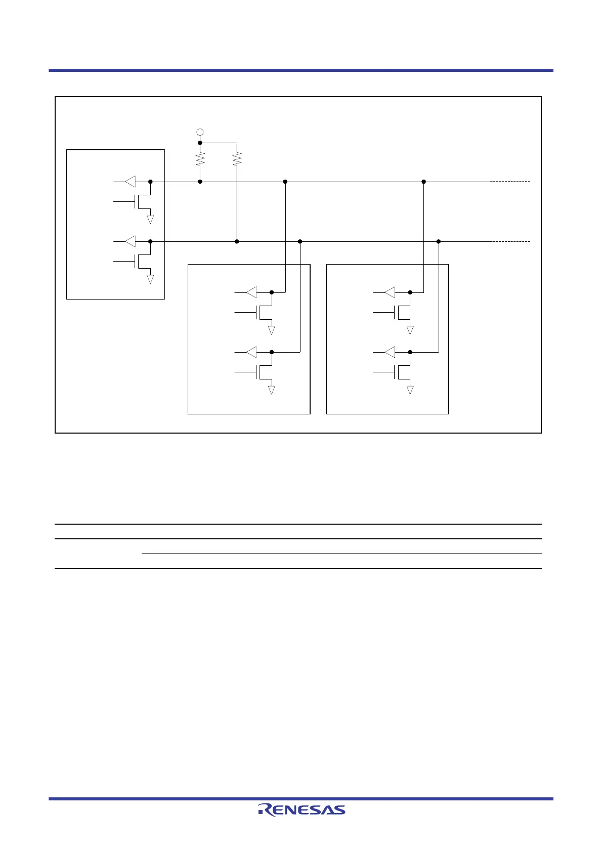
Figure 35.2 I/O Pin Connection to the External Circuit (I
2
C-bus Configuration Example)
The input level of the signals for RIIC is CMOS when I
2
C-bus is selected (ICMR3.SMBS bit is 0), or TTL when SMBus
is selected (ICMR3.SMBS bit is 1).
Table 35.2 RIIC Pin Configuration
Channel Pin Name I/O Function
RIIC0 SCL0 I/O RIIC0 serial clock I/O pin
SDA0 I/O RIIC0 serial data I/O pin
Power supply for pull-up (VCC to 5 V)
SCL
SDA
(Master)
(Slave 1)
SCL
SDA
(Slave 2)
SCL
SDA
SCL
SDA
SCLin
SDAin
SCLout#
SDAout#
SCLin
SDAin
SCLout#
SDAout#
SCLin
SDAin
SCLout#
SDAout#

 Loading...


