R01UH0823EJ0100 Rev.1.00 Page 306 of 1823
Jul 31, 2019
RX23W Group 16. Buses
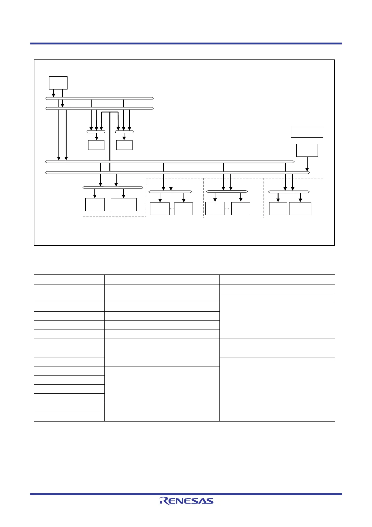
Figure 16.1 Bus Configuration
Table 16.2 Addresses Assigned for Each Bus
Address Bus Area
0000 0000h to 0000 FFFFh Memory bus 1 RAM
0001 0000h to 0007 FFFFh Reserved area
0008 0000h to 0008 7FFFh Internal peripheral bus 1 Peripheral I/O registers
0008 8000h to 0009 FFFFh Internal peripheral bus 2
000A 0000h to 000B FFFFh Internal peripheral bus 3
000C 0000h to 000D FFFFh Internal peripheral bus 4
000E 0000h to 000F FFFFh Reserved area Reserved area
0010 0000h to 007F FFFFh Internal peripheral bus 6 Flash control module and E2 DataFlash
0080 0000h to 00FF FFFFh Reserved area
0100 0000h to 04FF FFFFh Reserved area
0500 0000h to 07FF FFFFh
0800 0000h to 0FFF FFFFh
1000 0000h to 7FFF FFFFh
8000 0000h to FEFF FFFFh Memory bus 2 ROM
(for reading only)
FF00 0000h to FFFF FFFFh
Bus error monitoring
section
Internal main bus 1
Internal main bus 2
Instruction bus
Operand bus
ROM
RAM
Internal peripheral
bus 1
Internal peripheral
buses 2 and 3
DTC/DMAC(s)
ICLK synchronization
CPU
Peripheral
module
Peripheral
module
Peripheral
module
Memory bus 1
Memory bus 2
Flash
control
module
Internal peripheral
bus 6
Internal peripheral
bus 4
Operation synchronized with PCLKAOperation synchronized with PCLKB Operation synchronized with FCLK
DTC/
DMAC(m)
E2 DataFlash
Peripheral
module
Peripheral
module
Note1: The solid arrow indicates the direction of access request from the bus master.
Note2: DTC/DMAC(m) is used for bus mastership, while DTC/DMAC(s) is for register access.

 Loading...


