2 User Interface
2.16 Block Diagram
2.16 Block Diagram
When you press the Block Diagram button in the "Control Bar" on page 135, the
display changes to a stylized pictorial representation of the current internal
hardware setup and signal processing path. When you touch one of the blocks on
the Block Diagram, the corresponding menu panel opens.
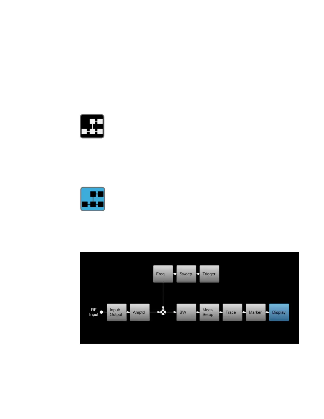
When you press the Block Diagram button, the display changes to a stylized
pictorial representation of the current internal hardware setup and signal
processing path. When you touch one of the blocks on the Block Diagram, the
corresponding menu panel opens.
While in the Block Diagram display, the button is blue colored, as:
To exit the Block Diagram display, tap the button again.
The Block Diagram display is not meant to be a completely accurate representation,
but one which can show differences as you change the hardware setup. For
example, here is the basic RF Block Diagram:
And here is the Block Diagram when External Mixing is selected:
Short Range Comms & IoT Mode User's &Programmer's Reference 151