3 Short-Range Comms & IoT Mode
3.9 Occupied BW Measurement
This is the setting parameter. See "% of OBW Power" on page 1294
x dB
This is the setting parameter. See "x dB" on page 1295.
Active Carriers
In the LTE-Advanced FDD/TDD and 5G NR modes, the number of active carriers is
displayed to show how many carriers are identified as active in auto detected mode
of span, otherwise “-” is displayed to indicate that it is out of scope. When there is
one active carrier, Transmit Freq Error is displayed. Otherwise, “---“ is displayed.
Measure Trace
See "Measure Trace" on page 1508.
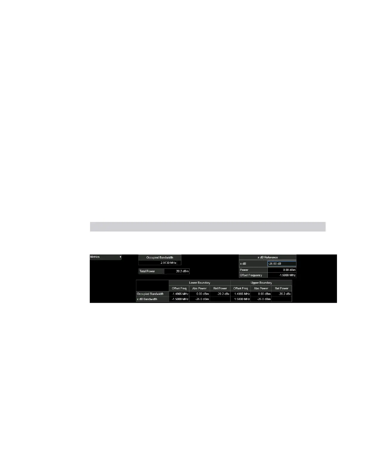
3.9.2.3 Metrics - OBW Boundaries
Window #3
Displays occupied bandwidth and X dB bandwidth for both lower and upper
boundaries.
View Size Position
"OBW Boundaries" on page 1220 Half, full width Bottom
Gate One third, full width Bottom
Occupied Bandwidth
The occupied bandwidth result is f
2
– f
1,
where f
1
and f
2
are the lower and upper
carrier boundary point. f
1
and f
2
are calculated with Occupied Bandwidth
algorithms.
Total Power or OBW Power
Total Power is the power integrated in the specified span setting. OBW Power is
calculated from multiplying the total power by OBW percent power. The user can
select the total power or the OBW power with the Power Ref control in Meas Setup.
x dB
This is the setting parameter. See "x dB" on page 1295.
x dB Ref Pwr
Short Range Comms & IoT Mode User's &Programmer's Reference 1223
 Loading...


