8 Trigger
8.1 Trigger
More Information
The graphic below shows the action of the periodic timer trigger.
A common application is measuring periodic burst RF signals for which a trigger
signal is not easily available. For example, we might be measuring a TDMA radio that
bursts every 20 ms. Let’s assume that the 20 ms period is very consistent. Let’s also
assume that we do not have an external trigger source available that is synchronized
with the period, and that the signal-to-noise ratio of the signal is not high enough to
provide a clean RF burst trigger at all of the analysis frequencies. For example, we
might want to measure spurious transmissions at an offset from the carrier that is
larger than the bandwidth of the RF burst trigger. In this application, we can set the
Periodic Timer to a 20.00 ms period and adjust the offset from that timer to position
our trigger just where we want it. If we find that the 20.00 ms is not exactly right, we
can adjust the period slightly to minimize the drift between the period timer and the
signal to be measured.
A second way to use this feature would be to use Sync Source temporarily, instead
of Offset. In this case, we might tune to the signal in a narrow span and use the RF
Burst trigger to synchronize the periodic timer. Then we would turn the sync source
off so that it would not miss-trigger. Miss-triggering can occur when we are tuned
so far away from the RF burst trigger that it is no longer reliable.
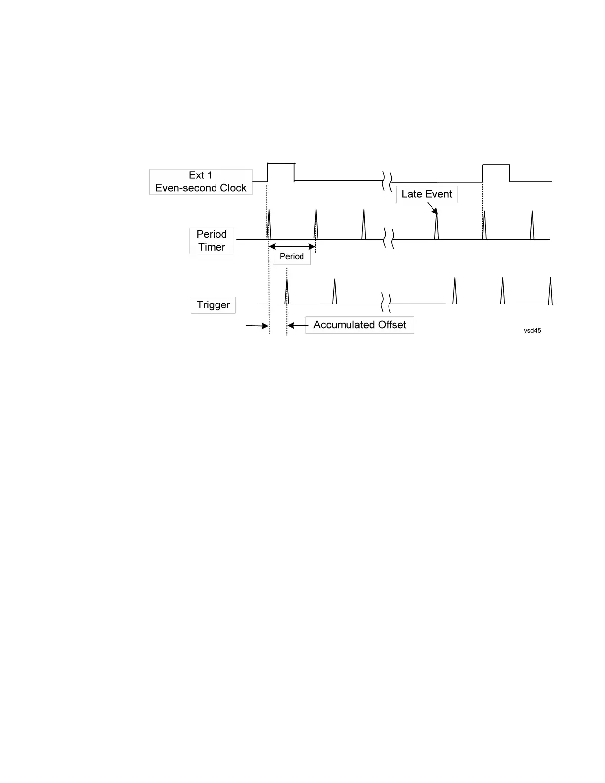
A third example would be to synchronize to a signal that has a reference time
element of much longer period than the period of interest. In some CDMA
applications, it is useful to look at signals with a short periodicity, by synchronizing
that periodicity to the "even-second clock" edge that happens every two seconds.
Thus, we could connect the even-second clock trigger to Ext1 and use then Ext1 as
the sync source for the periodic timer.
The figure below illustrates this third example. The top trace represents the even-
second clock. It causes the periodic timer to synchronize with the leading edge
2335 Short Range Comms & IoT Mode User's &Programmer's Reference
 Loading...


