3 Short-Range Comms & IoT Mode
3.6 Power Stat CCDF Measurement
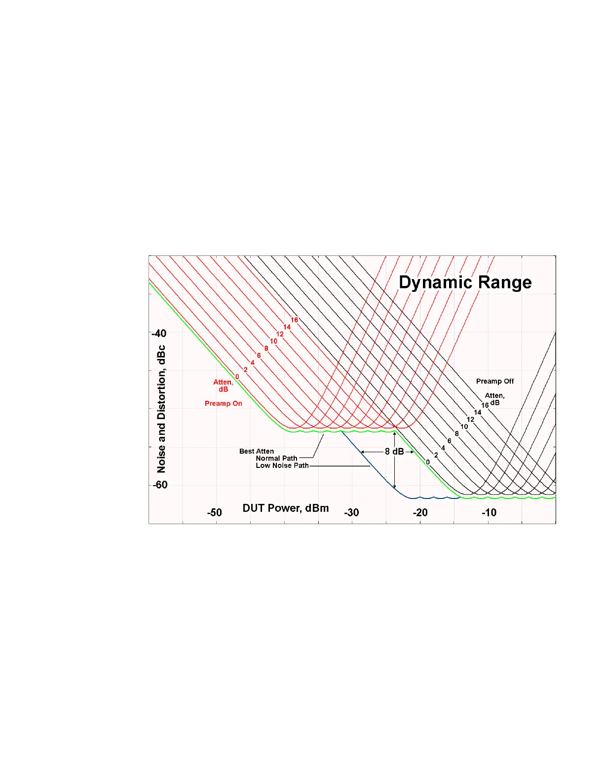
range of the preamp path is too little and the noise floor of the standard path is too
high, the Low Noise Path can provide the best dynamic range
The graph below illustrates the concept. It shows, in red, the performance of an
instrument at different attenuation settings, both with the preamp on and off, in a
measurement that is affected by both instrument noise and instrument TOI. The
green shows the best available dynamic range, offset by 0.5dB for clarity. The blue
shows how the best available dynamic range improves for moderate signal levels
with the low noise path switched in. In this illustration, the preamp improves the
noise floor by 15dB while degrading the third-order intercept by 30dB, and the low
noise path reduces loss by 8dB. The attenuator step size is 2dB.
There are other times where selecting the low noise path improves performance,
too. Compression-limited measurements such as finding the nulls in a pulsed-RF
spectrum can profit from the low noise path in a way similar to the TOI-limited
measurement illustrated. Accuracy can be improved when the low noise path allows
the optimum attenuation to increase from a small amount like 0, 2 or 4dB to a larger
amount, giving better return loss at the instrument input. Harmonic measurements,
such as second and third harmonic levels, are much improved using the low noise
path because of the superiority of that path for harmonic (though not
intermodulation) distortion performance.
726 Short Range Comms & IoT Mode User's &Programmer's Reference
 Loading...


