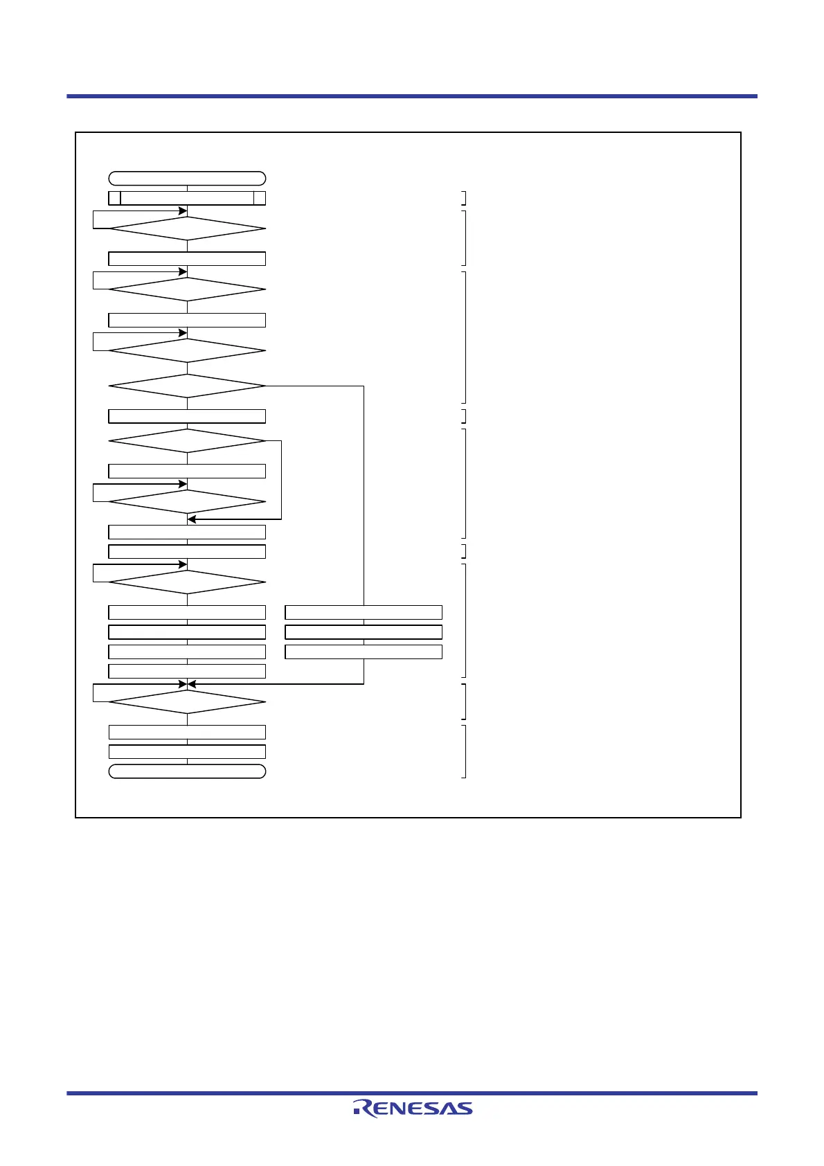
Master reception starts
Initial settings
ICCR2.BBSY = 0?
ICCR2.ST = 1
ICSR2.TDRE = 1?
Write the ICDRT register
ICSR2.RDRF = 1?
ICSR2.NACKF = 0?
ICMR3.WAIT = 1
Next data = last byte?
Dummy read the ICDRR register
ICSR2.RDRF = 1?
Read the ICDRR register
ICSR2.RDRF = 1?
No
Yes
No
Yes
No
Yes
No
Yes
Yes
No
No
Yes
No
ICSR2.STOP = 0
Yes
ICCR2.SP = 1
Read the ICDRR register
ICMR3.WAIT = 0
ICSR2.STOP = 0
ICCR2.SP = 1
Dummy read the ICDRR register
ICSR2.STOP = 1?
No
Yes
ICSR2.NACKF = 0
ICSR2.STOP = 0
Master reception ends
(1) Initial settings
(2) Check I
2
C-bus occupation and issue a start condition.
(3) Transmit the slave address followed by
R and check ACK.
(4) Set to WAIT
(5) Set to NACK
(When receiving 2 bytes, perform dummy
read.)
(6) Read received data
(When receiving 1 byte, perform
dummy read.)
(7) Read the last data,
release SCL by the ACKBT bit setting,
and issue a stop condition.
(8) Confirm that the stop condition
has been issued.
(9) Processing for the next transfer operation
Set ICMR3.ACKBT bit

 Loading...


