R01UH0823EJ0100 Rev.1.00 Page 1274 of 1823
Jul 31, 2019
RX23W Group 36. CAN Module (RSCAN)
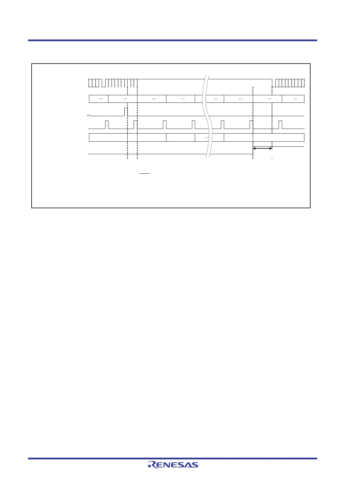
Figure 36.9 shows the interval timer timing chart.
Figure 36.9 Interval Timer Timing Chart
(1) The interval timer starts counting upon completion of transmission. Since the prescaler is not initialized at the time
of transmission completion, the first interval time contains an error of up to one count of the interval timer.
(2) The interval timer is decremented by the next count enable signal.
(3) When the interval timer has decreased to 0, the transmit/receive FIFO buffer issues a transmit request.
(4) The transmit/receive FIFO buffer is determined for the next transmission by the priority determination, it starts
transmitting data. Transmission starts with a delay of three CAN bit time clock cycles or less from the issue of
transmit request.
499 0 499 0 499 0 499 0 499 0 499 0 499 0 499 0
0 10 9 8 1 0
ITRCP[15:0]: Bits in the GCFGH register (The set value is 500 in this figure.)
CFITT[7:0]: Bits in the CFCCH0 register (The set value is 10 in this figure.)
SOF
(4)(3)(2)(1)
ACK
EOF INT
Transmit priority determination
and internal processing
Interval time (logical value) = × m (ITRCP[15:0] value) × CFITT[7:0] value
CAN bus
Prescaler of
ITRCP[15:0]
Transmit complete
signal
Count enable signal
Interval timer
FIFO transmit request
1
0
1
0
1
0
High
Low
1
PCLK

 Loading...


