R01UH0823EJ0100 Rev.1.00 Page 1273 of 1823
Jul 31, 2019
RX23W Group 36. CAN Module (RSCAN)
CFCCH0.CFITT[7:0] bits to 00h.
Select an interval timer count source by the CFCCH0.CFITR and CFITSS bits. When the CFCCH0.CFITR and CFITSS
bits are set to 00b, the clock obtained by frequency-dividing PCLK by the GCFGH.ITRCP[15:0] value is used as a count
source. When the CFCCH0.CFITR and CFITSS bits are set to 10b, the clock obtained by frequency-dividing PCLK by
the GCFGH.ITRCP[15:0] value ×10 is used as a count source. When the CFCCH0.CFITR and CFITSS bits are set to
x1b, the CAN bit time clock is used as a count source.
The interval time is calculated by the following equations where M is the set GCFGH.ITRCP[15:0] value and N is the set
CFCCH0.CFITT[7:0] value.
When CFCCH0.CFITR and CFITSS = 00b
When CFCCH0.CFITR and CFITSS = 10b
When CFCCH0.CFITR and CFITSS = x1b
(fCANBIT is CAN bit time clock frequency)
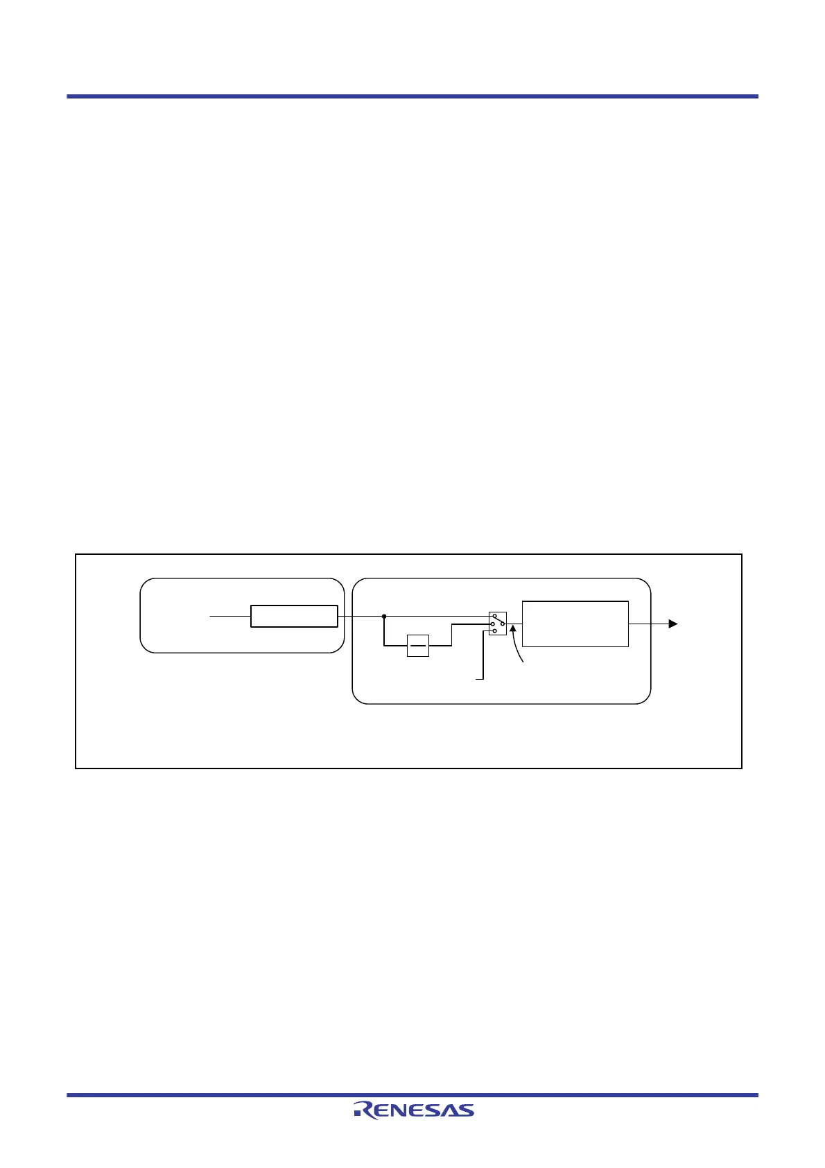
Figure 36.8 shows the interval timer block diagram.
Figure 36.8 Interval Timer Block Diagram
1
PCLK
----------------
M N
1
PCLK
----------------
M 10 N
1
fCANBIT
-------------------------
N
Prescaler
ITRCP[15:0]: Bits in the GCFGH register
CFITR, CFITSS, CFITT[7:0]: Bits in the CFCCH0 register
Interval timer
(Setting range: 0 to 255)
ITRCP[15:0]
PCLK
1
10
CAN bit time clock
Count enable signal
CFITR, CFITSS
00b
10b
x1b
CFITT[7:0]

 Loading...


