R01UH0823EJ0100 Rev.1.00 Page 1390 of 1823
Jul 31, 2019
RX23W Group 38. Serial Peripheral Interface (RSPIa)
(4) Burst Transfer
If the SPCMDm.SSLKP bit that the RSPI references during the current serial transfer is 1, the RSPI keeps the SSLAi
signal level during the serial transfer until the beginning of the SSLAi signal assertion for the next serial transfer. If the
SSLAi signal level for the next serial transfer is the same as the SSLAi signal level for the current serial transfer, the
RSPI can execute continuous serial transfers while keeping the SSLAi signal assertion status (burst transfer).
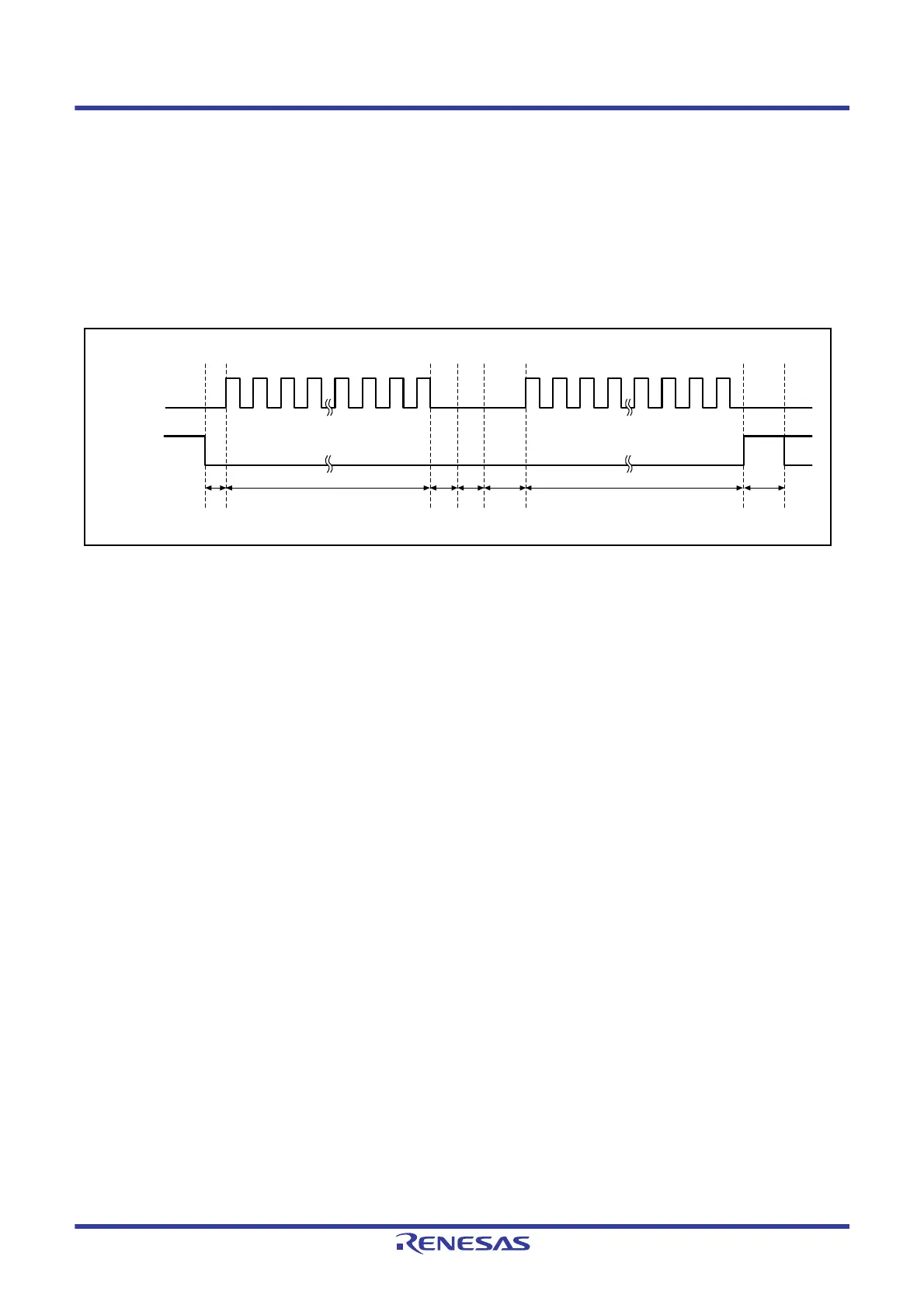
Figure 38.34 shows an example of an SSLAi signal operation for the case where a burst transfer is implemented using
SPCMD0 and SPCMD1 register settings. The text below explains the RSPI operations (1) to (7) as shown in
Figure
38.34
. It should be noted that the polarity of the SSLAi output signal depends on the SSLP register settings.
Figure 38.34 Example of Burst Transfer Operation Using SSLKP Bit
(1) Based on SPCMD0, the RSPI asserts the SSLAi signal and inserts RSPCK delays.
(2) The RSPI executes serial transfers according to SPCMD0.
(3) The RSPI inserts SSL negation delays.
(4) Since the SPCMD0.SSLKP bit is 1, the RSPI keeps the SSLAi signal value on SPCMD0. This period is sustained,
at the shortest, for a period equal to the next-access delay of SPCMD0. If the shift register is empty after the passage
of a minimum period, this period is sustained until the transmit data is stored in the shift register for the next
transfer.
(5) Based on SPCMD1, the RSPI asserts the SSLAi signal and inserts RSPCK delays.
(6) The RSPI executes serial transfers according to SPCMD1.
(7) Because the SPCMD1.SSLKP bit is 0, the RSPI negates the SSLAi signal. In addition, a next-access delay is
inserted according to SPCMD1.
If the SSLAi signal output settings in the SPCMDm register in which 1 is assigned to the SSLKP bit are different from
the SSLAi signal output settings in the SPCMDm register to be used in the next transfer, the RSPI switches the SSLAi
signal status to SSLAi signal assertion ((5) in
Figure 38.34) corresponding to the command for the next transfer. Note
that if such an SSLAi signal switching occurs, the slaves that drive the MISOA signal compete, and collision of signal
levels may occur.
The RSPI in master mode references the SSLAi signal operation within the module for the case where the SSLKP bit is
not used. Even when the SPCMDm.CPHA bit is 0, the RSPI can accurately start serial transfers by using the SSLAi
signal assertion for the next transfer that is detected internally.
RSPCKn
SSLin
(CPHA = 1,
CPOL = 0)
(1) (2) (3) (4) (5) (6) (7)
 Loading...


