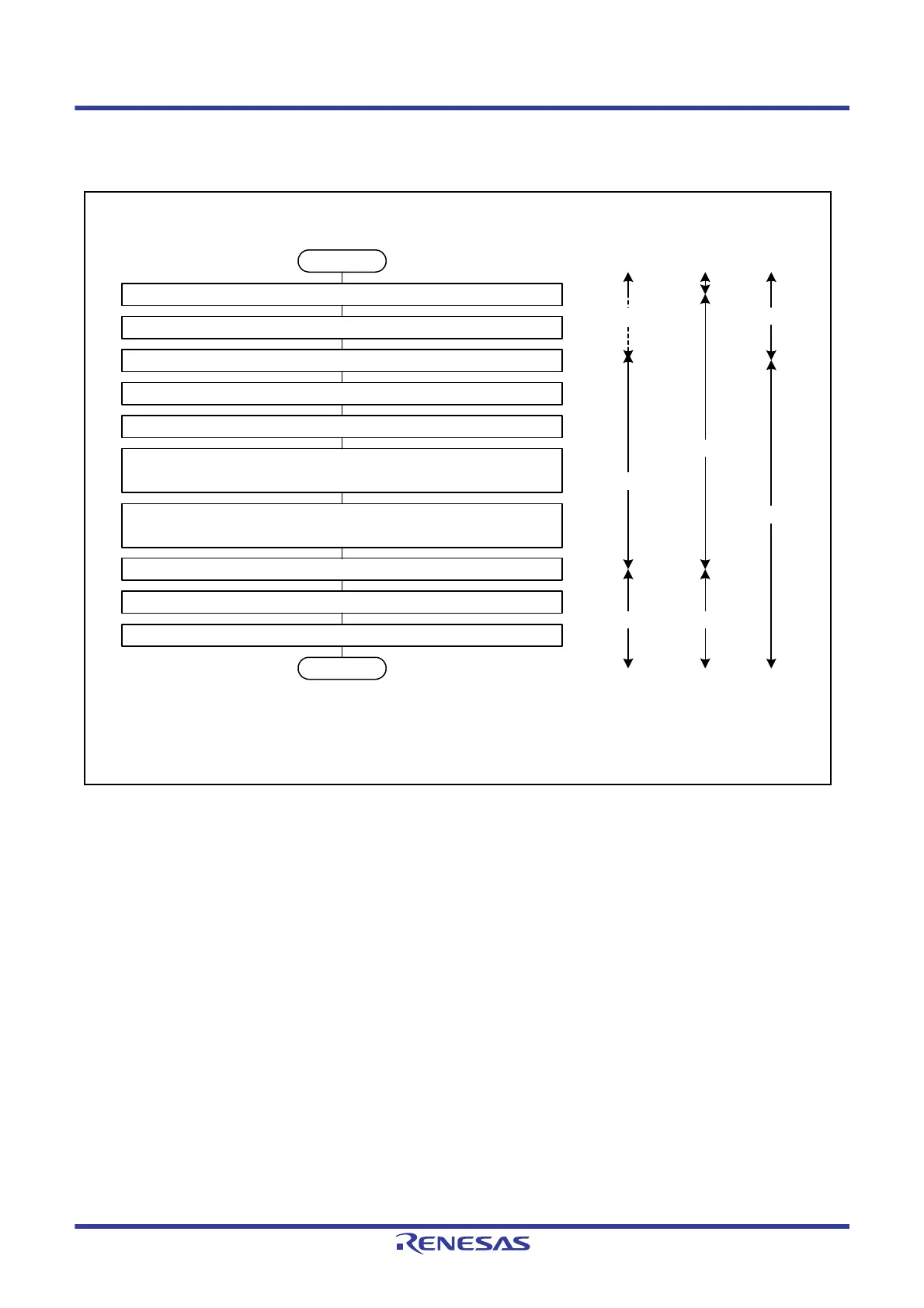
Start
Set the SOSCCR.SOSTP bit to 1 (sub-clock oscillator is stopped).
Read the SOSCCR.SOSTP bit and confirm that it is 1.
Set the RCR3.RTCEN bit to 0 (sub-clock oscillator is stopped).
Read the RCR3.RTCEN bit and confirm that it is 0.
*1
Wait for at least five cycles (about 153 µs) of the sub-clock to elapse.
Set bit 3 to bit 1 in the RCR3 register (or the RCR3.RTCDV[2:0] bits) to
001b or 110b.
Read bit 3 to bit 1 in the RCR3 register (or the RCR3.RTCDV[2:0] bits) and
confirm that they have been rewritten.
Set the SOSCCR.SOSTP bit to 0 (sub-clock oscillator is operating).
Read the SOSCCR.SOSTP bit and confirm that it is 0.
Wait for the oscillation stabilization time of the sub-clock to elapse by software.
End
Sub-clock
oscillation state
SOSCCR.
SOSTP
RCR3.
RTCEN
0
Undefined
0
1
0
Note 1. The values of bit 7 to bit 1 are undefined. Confirm only the value of the RCR3.RTCEN bit.
Oscillating
Stopped
Oscillating

 Loading...


