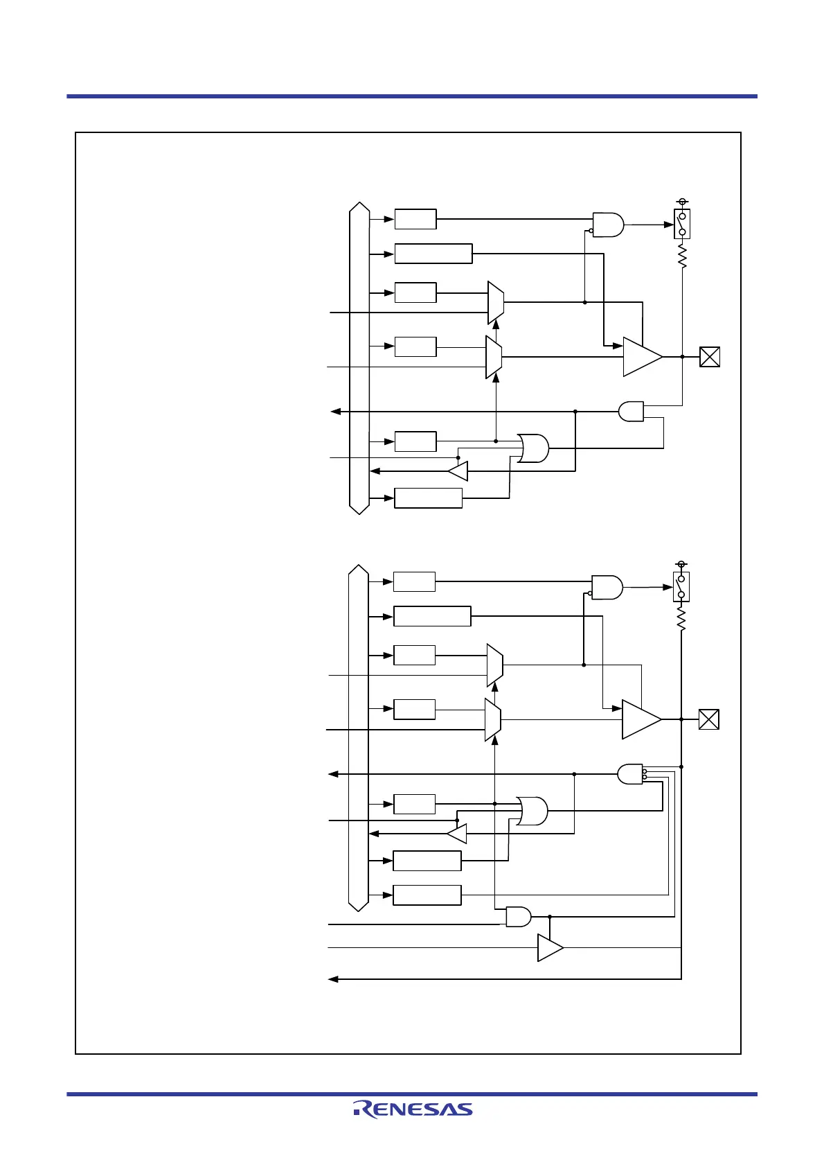
EasyManuals Logo

Renesas RX Series User Manual

Renesas RX Series
1823 pages
To Next Page IconTo Next Page
To Previous Page IconTo Previous Page
Page #433 background imageLoading...
Page #433 background image
R01UH0823EJ0100 Rev.1.00 Page 433 of 1823
Jul 31, 2019
RX23W Group 21. I/O Ports
Figure 21.2 I/O Port Configuration (2)
Port 1: P16, P17
Port J: PJ3
Peripheral module output signal
Reading the port
PMR
ODR0, ODR1
PDR
PODR
Enable peripheral module output
Input signal of peripheral module/interrupt
PCR
*1
0
1
0
1
ISEL bit
1: ON
0: OFF
Port 1: P14, P15
Peripheral module output signal
Reading the port
PMR
ODR0, ODR1
PDR
PODR
Enable peripheral module output
Input signal of peripheral module/interrupt
PCR
*1
0
1
0
1
ISEL bit
*2
1: ON
0: OFF
CTSU channel enable control register
Sensor drive pulse
ASEL bit
*2
Note 1. Control signal for N-channel open-drain output
Note 2. An external interrupt function is multiplexed on this pin
Internal bus
Internal bus
Analog input

Table of Contents

Questions and Answers:

Question and Answer IconNeed help?

Do you have a question about the Renesas RX Series and is the answer not in the manual?

Renesas RX Series Specifications

General IconGeneral
CoreRXv1, RXv2, RXv3
Flash MemoryUp to 8 MB
RAMUp to 1 MB
Operating Voltage1.62V to 5.5V
Operating Temperature-40°C to +85°C or +105°C
PackageBGA, LQFP
ADC Resolution12-bit
DAC Resolution12-bit
Communication InterfacesSCI, SPI, I2C, USB, Ethernet, CAN
Architecture32-bit
Security FeaturesMemory Protection Unit (MPU)

Related product manuals