R01UH0823EJ0100 Rev.1.00 Page 505 of 1823
Jul 31, 2019
RX23W Group 23. Multi-Function Timer Pulse Unit 2 (MTU2a)
Note: The initial output value of negative-phase waveform changes to an active level after the dead time has passed since counting
starts.
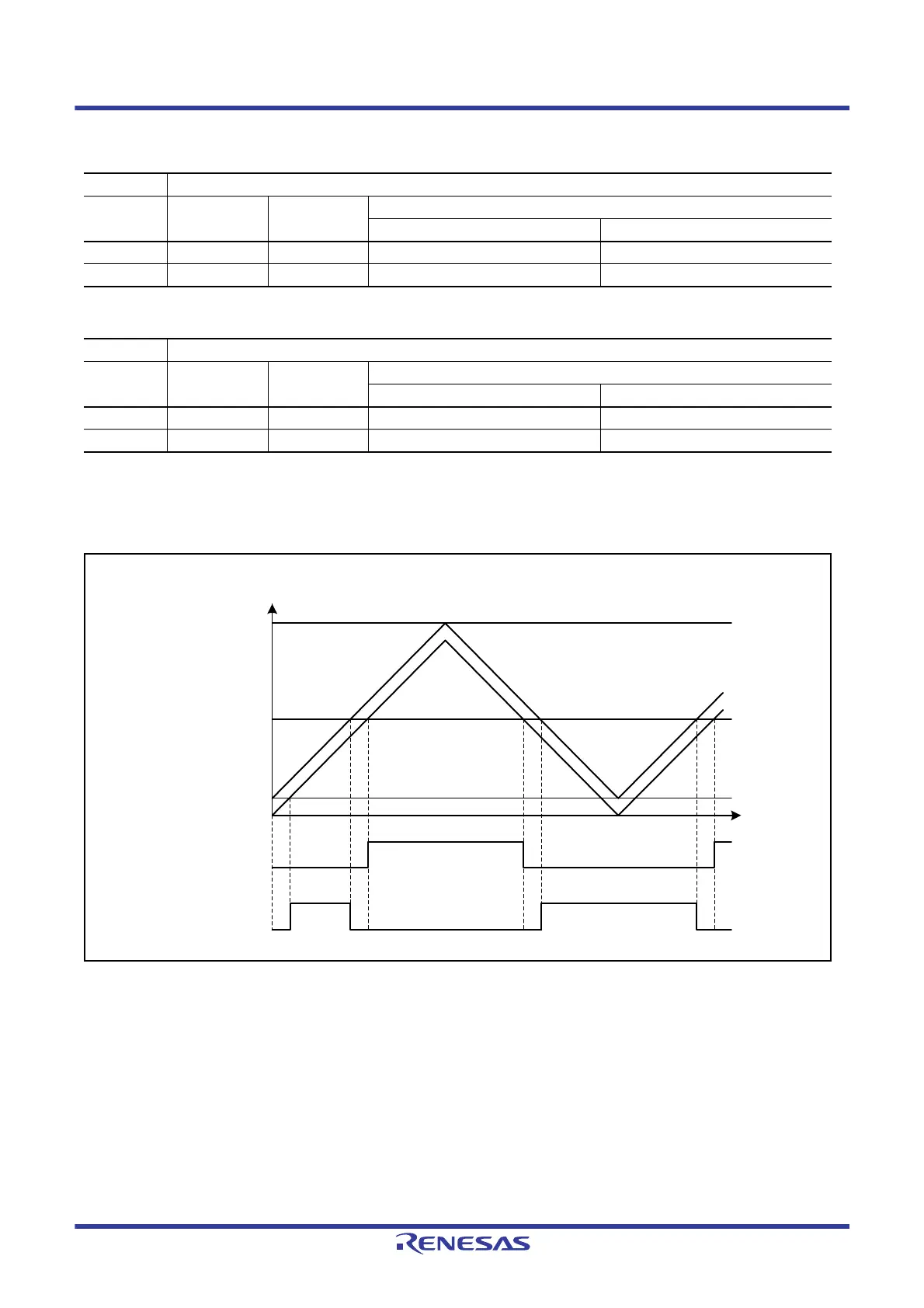
Figure 23.2 shows an example of output in complementary PWM mode (one phase) when OLSN = 1 and OLSP = 1.
Figure 23.2 Example of Output in Complementary PWM Mode
Table 23.27 Output Level Select Function
Bit 0 Function
OLSP Initial Output Active Level
Compare Match Output
Up-Counting Down-Counting
0 High Low Low High
1 Low High High Low
Table 23.28 Output Level Select Function
Bit 1 Function
OLSN Initial Output Active Level
Compare Match Output
Up-Counting Down-Counting
0 High Low High Low
1 Low High Low High
MTU3.TCNT value
MTU3.TGRA
MTU4.TGRA
TDDR
0000h
Time
MTU4.TCNT
MTU3.TCNT
Positive-phase output
Negative-phase output
Active level
Compare match
output (up-count)
Initial
output
Initial
output
Compare match output
(down-count)
Compare match
output (up-count)
Compare match output
(down-count)
Active level
Active
level

 Loading...


