R01UH0823EJ0100 Rev.1.00 Page 538 of 1823
Jul 31, 2019
RX23W Group 23. Multi-Function Timer Pulse Unit 2 (MTU2a)
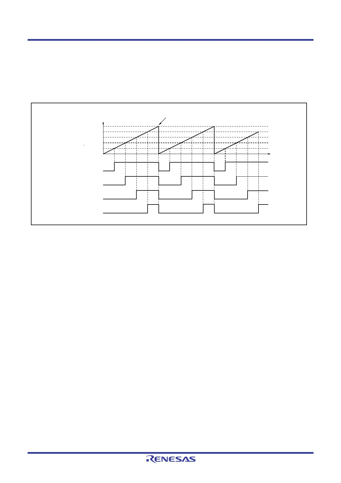
Figure 23.27 shows an example of operation in PWM mode 2.
In this example, synchronous operation is designated for MTU0 and MTU1, MTU1.TGRB compare match is set as the
TCNT clearing source, and a low level is set as the initial output value and a high level as the output value for the other
TGR registers (MTU0.TGRA to MTU0.TGRC and MTU1.TGRA), outputting 4-phase PWM waveforms.
In this case, the value set in the MTU1.TGRB register is used as the cycle, and the values set in the other TGR registers
are used as the duty.
Figure 23.27 Example of PWM Mode Operation
Time
TCNT value Counter cleared by MTU1.TGRB compare match
0000h
MTIOC0A
MTIOC0B
MTIOC0C
MTIOC1A
MTU1.TGRB
MTU1.TGRA
MTU0.TGRC
MTU0.TGRB
MTU0.TGRA

 Loading...


