R01UH0823EJ0100 Rev.1.00 Page 581 of 1823
Jul 31, 2019
RX23W Group 23. Multi-Function Timer Pulse Unit 2 (MTU2a)
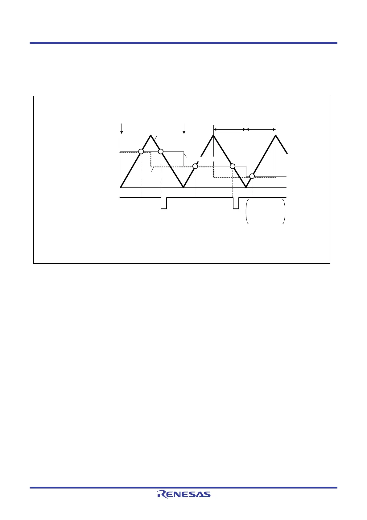
(2) Basic Example of A/D Converter Start Request Delaying Function Operation
Figure 23.74 shows a basic example of A/D converter start request signal (TRG4AN) operation when the trough of the
MTU4.TCNT counter is specified for the buffer transfer timing and an A/D converter start request signal is output during
MTU4.TCNT down-counting.
Figure 23.74 Basic Example of A/D Converter Start Request Signal (TRG4AN) Operation
(3) Period in Which A/D Converter Start Requests are Enabled
When the MTU4.TCNT counter and the MTU4.TADCORA or MTU4.TADCORB register match within the period
enabled by the UT4AE and UT4BE bits, the corresponding A/D converter start request (TRG4AN or TRG4BN) is
issued.
When the UT4AE and UT4BE bits in the MTU4.TADCR register are set to 1 in complementary PWM mode, A/D
converter start requests are enabled during the MTU4.TCNT up-counting (0 ≤ MTU4.TCNT ≤ TCDR – 1). When the
DT4AE and DT4BE bits in the MTU4.TADCR register are set to 1, A/D converter start requests are enabled during
MTU4.TCNT down-counting (TCDR ≥ MTU4.TCNT ≥ 1). Refer to
Figure 23.74.
(4) Buffer Transfer
The data in the timer A/D converter start request cycle set registers (MTU4.TADCORA and MTU4.TADCORB) is
updated by writing data to the timer A/D converter start request cycle set buffer registers (MTU4.TADCOBRA and
MTU4.TADCOBRB). Data is transferred from the buffer registers to the respective cycle set registers at the timing
selected with the MTU4.TADCR.BF[1:0] bits.
There are notes on the timing for transferring data when using buffer transfer in complementary PWM mode.
For details,
section 23.6.26, Usage Notes on A/D Converter Delaying Function in Complementary PWM Mode.
In modes other than complementary PWM mode, set the BF[1] bit in the MTU4.TADCR register to 0.
MTU4.TCNT
Transfer from cycle buffer
register to cycle register
Transfer from cycle buffer
register to cycle register
Period in which A/D
converter start
requests are enabled
(DT4AE = 1)
A/D converter start
request (TRG4AN)
Complementary
PWM mode
UT4AE = 0
DT4AE = 1
BF[1:0] = 10b
Period in which A/D converter start requests are enabled (UT4AE = 1): 0 MTU4.TCNT TCDR – 1
Period in which A/D converter start requests are enabled (DT4AE = 1): TCDR
MTU4.TCNT 1
UT4AE, DT4AE, BF[1:0]: Bits in TADCR
Period in which A/D
converter start
requests are enabled
(UT4AE = 1)
MTU4.TADCOBRA
MTU4.TADCORA

 Loading...


