R01UH0823EJ0100 Rev.1.00 Page 620 of 1823
Jul 31, 2019
RX23W Group 23. Multi-Function Timer Pulse Unit 2 (MTU2a)
(10) Operation When Error Occurs in PWM Mode 1 and Operation is Restarted in Phase Counting
Mode
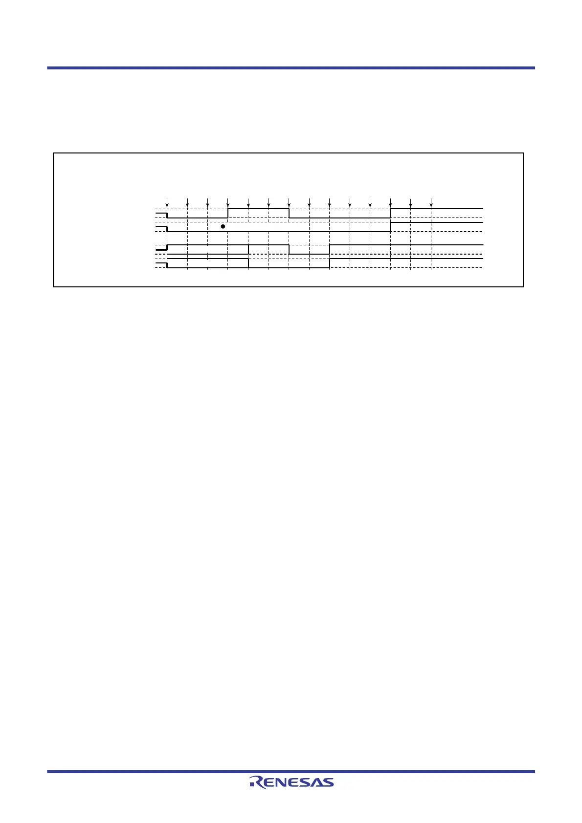
Figure 23.125 shows a case in which an error occurs in PWM mode 1 and operation is restarted in phase counting mode
after re-setting.
Figure 23.125 Error Occurrence in PWM Mode 1, Recovery in Phase Counting Mode
(1) to (10) are the same as in Figure 23.122.
(11) Set the phase counting mode.
(12) Initialize the pins with the TIOR register.
(13) Use the MPC and the port mode register (PMR) for the I/O port to set up MTU output.
(14)Restart operation by setting the TSTR register.
Note: The phase counting mode can only be selected for MTU1 and MTU2, and therefore the TOER register setting is
not necessary.
(1)
Reset
MTU module output
(2)
TMDR
(PWM1)
(3)
TOER
(1)
(4)
TIOR
(1 init
0 out)
(6)
TSTR
(1)
(7)
Match
(8)
Error
occurs
(9)
Port
output
(10)
TSTR
(0)
(11)
TMDR
(PCM)
(12)
TIOR
(1 init
0 out)
(14)
TSTR
(1)
PORT output
Pxx
Pxx
MTIOCnA
MTIOCnB
(5)
MPC
(MTU)
(13)
MPC
(MTU)
Not initialized (MTIOCnB)
Hi-Z
Hi-Z

 Loading...


