9 Programming the Instrument
9.4 Status Register System & STATus Subsystem
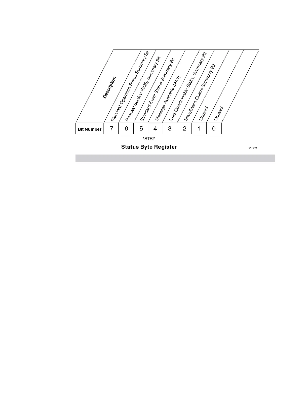
Bit Description
0, 1 These bits are always set to 0
2 A 1 in this bit position indicates that the SCPI error queue is not empty which means that it
contains at least one error message
3 A 1 in this bit position indicates that the data questionable summary bit has been set. The
data questionable event register can then be read to determine the specific condition that
caused this bit to be set
4 A 1 in this bit position indicates that the instrument has data ready in the output queue.
There are no lower status groups that provide input to this bit
5 A 1 in this bit position indicates that the standard event summary bit has been set. The
standard event status register can then be read to determine the specific event that caused
this bit to be set
6 A 1 in this bit position indicates that the instrument has at least one reason to report a
status change. This bit is also called the master summary status bit (MSS)
7 A 1 in this bit position indicates that the standard operation summary bit has been set. The
standard operation event register can then be read to determine the specific condition that
caused this bit to be set
To query the Status Byte Register, send "*STB? - Status Byte Query" on page 2428.
The response will be the decimal sum of the bits that are set to 1. For example, if bit
number 7 and bit number 3 are set to 1, the decimal sum of the 2 bits is 128 plus 8,
so the decimal value 136 is returned.
*STB does not clear the status register.
The RQS bit is read and reset by a serial poll. The same bit position (MSS) is read non-
destructively by *STB?. If you serial-poll bit 6, it is read as RQS, but if you send *STB,
it reads bit 6 as MSS. For more information refer to Section 11 of: IEEE Standard
488.2–1992
2461 Short Range Comms & IoT Mode User's &Programmer's Reference
 Loading...


