R01UH0823EJ0100 Rev.1.00 Page 1027 of 1823
Jul 31, 2019
RX23W Group 33. Serial Communications Interface (SCIg, SCIh)
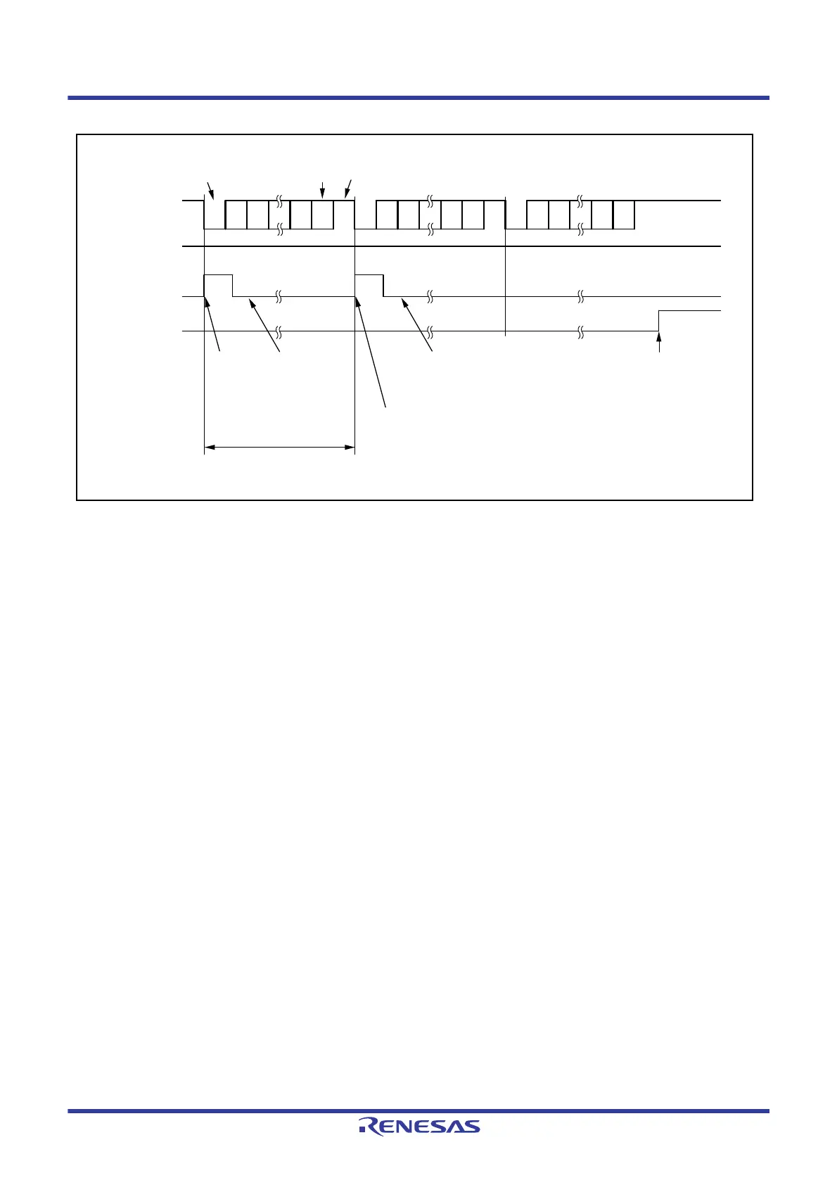
Figure 33.12 Example of Operation for Serial Transmission in Asynchronous Mode (3)
(with 8-Bit Data, Parity, 1 Stop Bit, CTS Function Not Used, from the Middle of Transmission until
Transmission Completion)
TXI interrupt flag
(IRn in ICU
*1
)
1 frame
Data
Parity bit Stop bitStart bit
Idle state
(mark state)
TEI interrupt
request generated
TXI interrupt request
generated
TXI interrupt
request generated
Data written to TDR in
TXI interrupt handling
routine
SSR.TEND flag
(TIE = 1)
(TIE = 0)
0D0
D7 0/1 1 0 D0 D1 D7
0/1D7
0/1 1
0D0
1
D1 D1
Data written to TDR in TXI interrupt
handling routine
(Set the TIE bit to 0 and the TEIE bit to
1 after writing the last data)
1
SCR.TE bit
Note 1. Refer to section 15, Interrupt Controller (ICUb) for details on the corresponding interrupt vector number.

 Loading...


