R01UH0823EJ0100 Rev.1.00 Page 1534 of 1823
Jul 31, 2019
RX23W Group 44. 12-Bit A/D Converter (S12ADE)
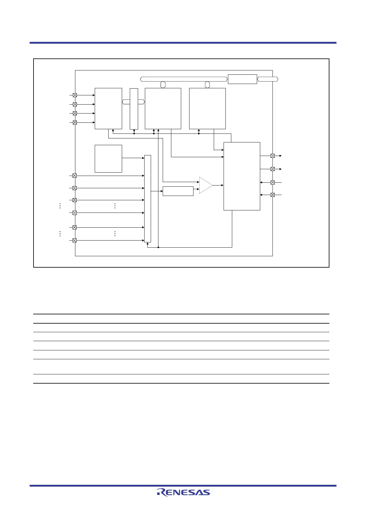
Figure 44.1 Block Diagram of 12-Bit A/D Converter
Table 44.3 lists the input pins of the 12-bit A/D converter.
Table 44.3 Pin Configuration of 12-Bit A/D Converter
Pin Name I/O Function
AVCC0 Input Analog block power supply pin
AVSS0 Input Analog block ground pin
VREFH0 Input Reference power supply pin
VREFL0 Input Reference power supply ground pin
AN000 to AN007, AN016 to AN020,
AN027
Input Analog input pins 0 to 7, analog input pins 16 to 20 and 27
ADTRG0# Input External trigger input pin for starting A/D conversion
12-bit D/A A/D control register
Bus interface
Control circuit
(including decoder)
A/D data register
Sample and hold
circuit
-
+
AVCC0
AVSS0
VREFH0
VREFL0
Comparator
Successive approximation
register
Analog multiplexer
Power
generator
for self-
diagnosis
Interrupt signal
(S12ADI0, GBADI)
Synchronous trigger
(MTU, TPU, ELC)
Asynchronous trigger
(ADTRG0#)
Output event signal to
ELC
AN020
AN016
AN007
AN000
Internal reference
power voltage
AN027

 Loading...


