R01UH0823EJ0100 Rev.1.00 Page 1754 of 1823
Jul 31, 2019
RX23W Group 51. Electrical Characteristics
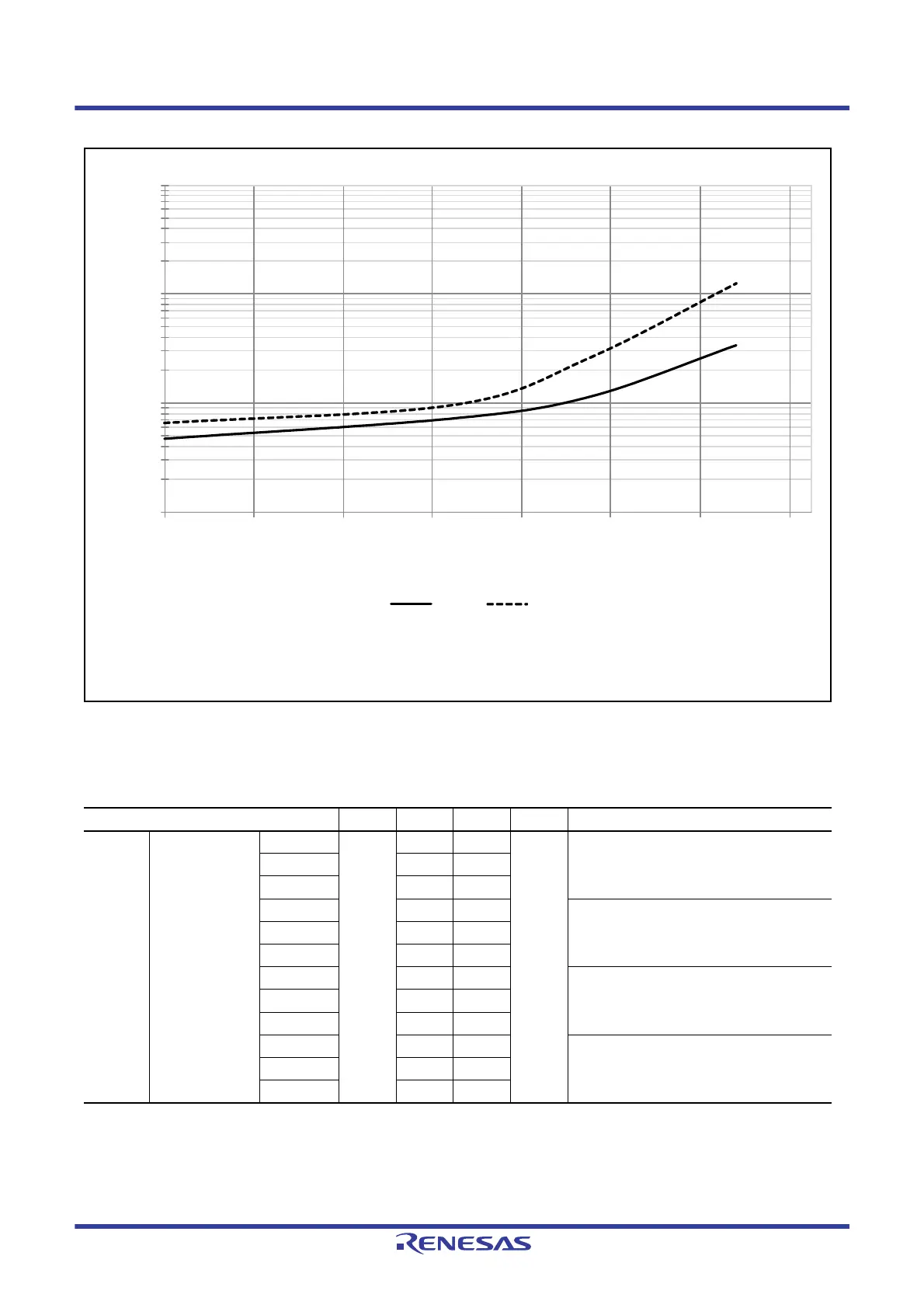
Figure 51.5 Temperature Dependency in Software Standby Mode (Reference Data)
Note 1. Supply current values do not include output charge/discharge current from all pins. The values apply when internal pull-up
MOSs are in the off state.
Table 51.9 DC Characteristics (7)
Conditions: 1.8 V ≤ VCC = VCC_USB = AVCC0 = VCC_RF = AVCC_RF ≤ 3.6 V, VSS = AVSS0 = VSS_USB = VSS_RF = 0 V,
T
a
= –40 to +85°C
Item Symbol Typ. Max. Unit Test Conditions
Supply
current*
1
RTC operation
when VCC is off
T
a
= 25°C I
CC
0.8 — μA VBATT = 2.0 V
RCR3.RTCDV[2:0] set to low drive capacity
T
a
= 55°C 0.9 —
T
a
= 85°C 1.0 —
T
a
= 25°C 0.9 — VBATT = 3.3 V
RCR3.RTCDV[2:0] set to low drive capacity
T
a
= 55°C 1.0 —
T
a
= 85°C 1.1 —
T
a
= 25°C 1.5 — VBATT = 2.0 V
RCR3.RTCDV[2:0] set to normal drive
capacity
T
a
= 55°C 1.8 —
T
a
= 85°C 2.1 —
T
a
= 25°C 1.6 — VBATT = 3.3 V
RCR3.RTCDV[2:0] set to normal drive
capacity
T
a
= 55°C 1.9 —
T
a
= 85°C 2.2 —
Note 1. Average value of the tested middle samples during product evaluation.
Note 2. Average value of the tested upper-limit samples during product evaluation.
0.1
1
10
100
–40 –20 0 20 40 60 80 100
ICC (µA)
Ta (°C)
*2
*1
*1 *2

 Loading...


