R01UH0823EJ0100 Rev.1.00 Page 1775 of 1823
Jul 31, 2019
RX23W Group 51. Electrical Characteristics
Note 1. The sub-clock continues oscillating in software standby mode during low-speed mode.
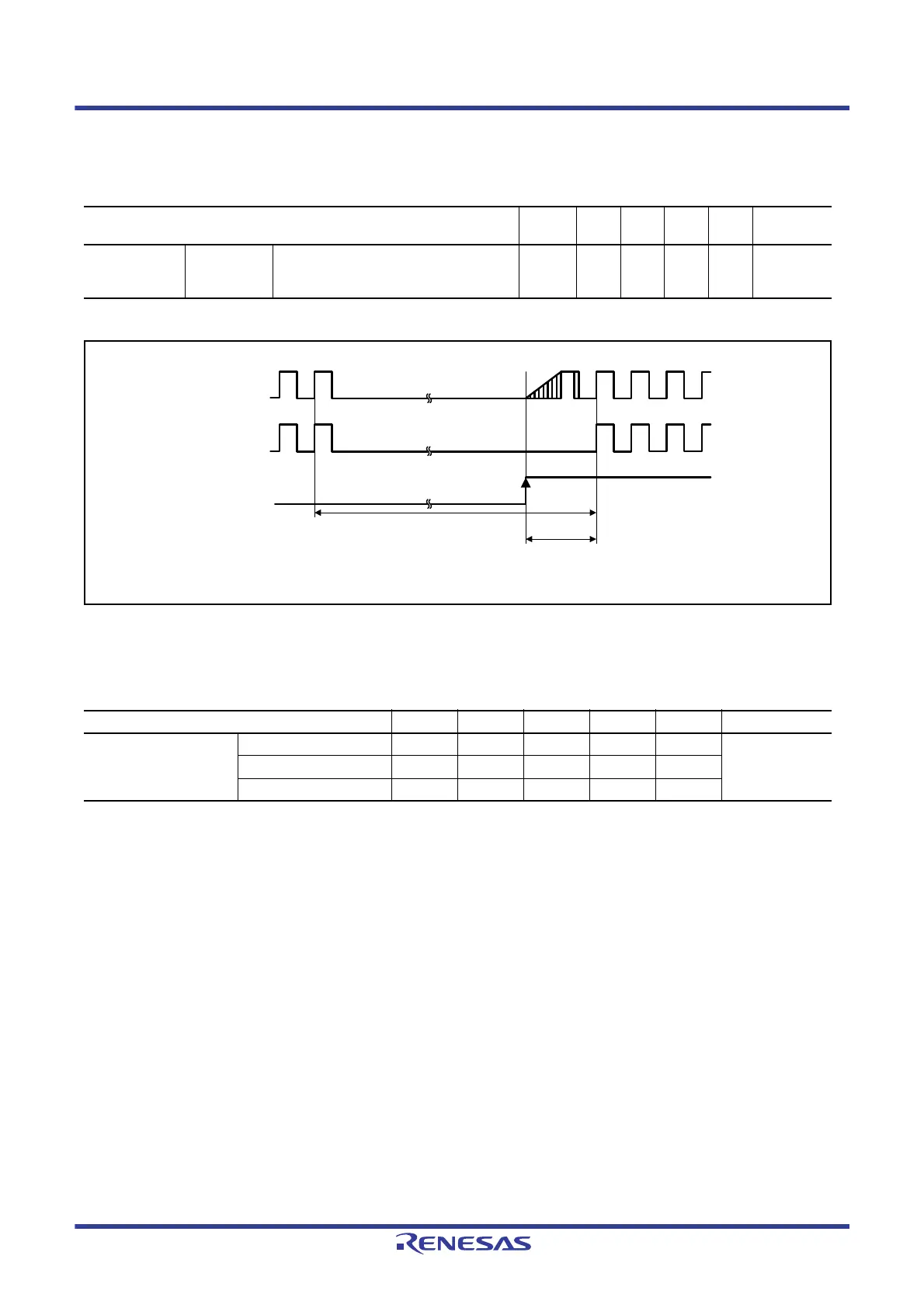
Figure 51.30 Software Standby Mode Recovery Timing
Note 1. Oscillators continue oscillating in deep sleep mode.
Note 2. When the frequency of the system clock is 32 MHz.
Note 3. When the frequency of the system clock is 12 MHz.
Note 4. When the frequency of the system clock is 32 kHz.
Table 51.28 Timing of Recovery from Low Power Consumption Modes (3)
Conditions: 1.8 V ≤ VCC = VCC_USB = AVCC0 = VCC_RF = AVCC_RF ≤ 3.6 V, VSS = AVSS0 = VSS_USB = VSS_RF = 0 V,
T
a
= –40 to +85°C
Item Symbol Min. Typ. Max. Unit
Test
Conditions
Recovery time
from software
standby mode*
1
Low-speed
mode
Sub-clock oscillator operating t
SBYSC
— 600 750 μs Figure 51.30
Table 51.29 Timing of Recovery from Low Power Consumption Modes (4)
Conditions: 1.8 V ≤ VCC = VCC_USB = AVCC0 = VCC_RF = AVCC_RF ≤ 3.6 V, VSS = AVSS0 = VSS_USB = VSS_RF = 0 V,
T
a
= –40 to +85°C
Item Symbol Min. Typ. Max. Unit Test Conditions
Recovery time from deep
sleep mode*
1
High-speed mode*
2
t
DSLP
— 2 3.5 μs Figure 51.31
Middle-speed mode*
3
t
DSLP
—3 4μs
Low-speed mode*
4
t
DSLP
— 400 500 μs
Oscillator
ICLK
IRQ
Software standby mode
t
SBYMC,
t
SBYPC,
t
SBYEX,
t
SBYPE,
t
SBYSC,
t
SBYHO,
t
SBYLO

 Loading...


