R01UH0823EJ0100 Rev.1.00 Page 568 of 1823
Jul 31, 2019
RX23W Group 23. Multi-Function Timer Pulse Unit 2 (MTU2a)
Example of Procedure for Setting Output Waveform Control at Synchronous Counter Clearing in
Complementary PWM Mode
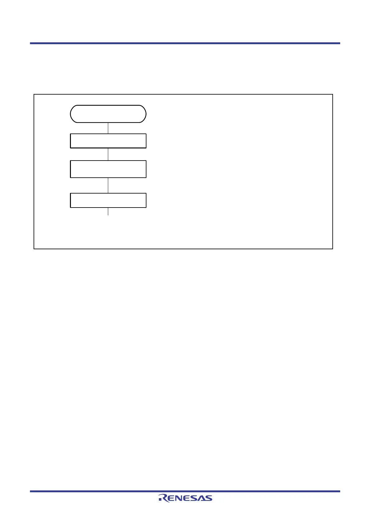
An example of the procedure for setting output waveform control at synchronous counter clearing in complementary
PWM mode is shown in
Figure 23.57.
Figure 23.57 Example of Procedure for Setting Output Waveform Control at Synchronous Counter Clearing in
Complementary PWM Mode
Examples of Output Waveform Control at Synchronous Counter Clearing in Complementary PWM Mode
Figure 23.58
to Figure 23.61 show examples of output waveform control in which the MTU operates in
complementary PWM mode and synchronous counter clearing is generated while the TWCR.WRE bit is set to 1. In the
examples shown in
Figure 23.58 to Figure 23.61, synchronous counter clearing occurs at timing (3), (6), (8), and (11)
shown in
Figure 23.56, respectively.
Stop count operation
Output waveform control at
synchronous counter clearing
Set TWCR and
complementary PWM mode
Start count operation
Output waveform control at
synchronous counter clearing
[1]
[2]
[3]
[1] Set bits CST3 and CST4 in the TSTR register to 0
to stop count operation. Specify the TWCR
register while counters MTU3.TCNT and
MTU4.TCNT are stopped.
[2] Read the TWCR.WRE bit and then write 1 to it to
suppress initial value output at counter clearing.
[3] Set bits CST3 and CST4 in the TSTR register to 1
simultaneously to start count operation.

 Loading...


