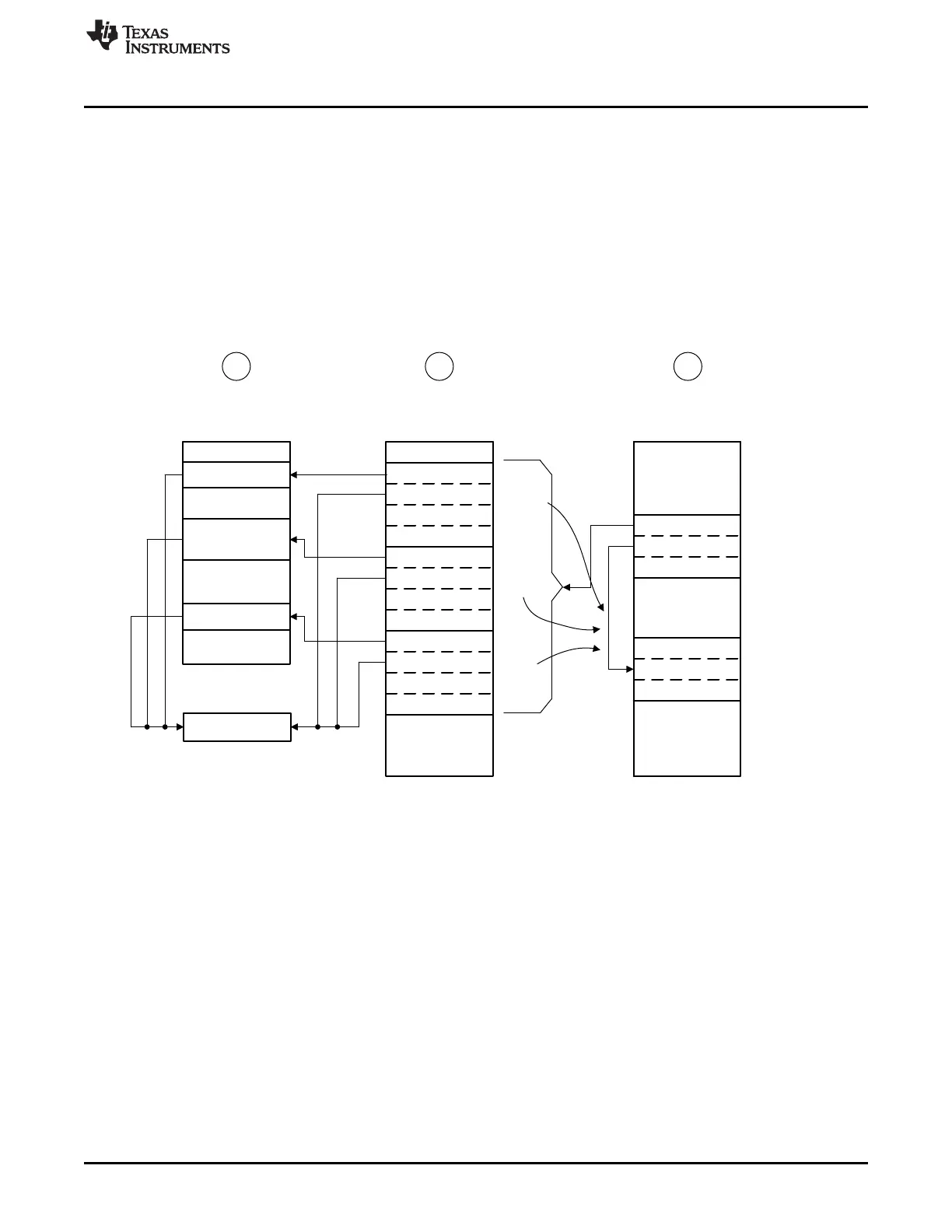
4 WORDS (SRC A)
16 WORDS (SRC B)
1 WORDS (SRC C)
SRC
DST
ITEMS = 1
Unused
SRC
DST
ITEMS = 16
Unused
SRC
DST
ITEMS = 4
Unused
A
B
C
SRC
DST
ITEMS = n
SRC
DST
ITEMS = 12
Channel Primary
Control Structure
Channel Alternate
Control Structure
³7$6.´$
³7$6.´%
³7$6.´&
Source Buffer in Memory Task List in Memory
Channel Control
Table In Memory
1 2 3
DEST
Peripheral Data
Register
www.ti.com
Functional Description
125
SWRU543–January 2019
Submit Documentation Feedback
Copyright © 2019, Texas Instruments Incorporated
Direct Memory Access (DMA)
4.2.5.6 Peripheral Scatter-Gather Mode
Peripheral scatter-gather mode is very similar to memory scatter-gather mode, except that the transfers
are controlled by a peripheral making a µDMA request. Upon detecting a request from the peripheral, the
µDMA controller uses the primary control structure to copy one entry from the list to the alternate control
structure, and then performs the transfer. At the end of this transfer, the next transfer is started only if the
peripheral again asserts a µDMA request. The µDMA controller continues to perform transfers from the list
only when the peripheral is making a request, until the last transfer is complete. A completion interrupt is
generated only after the last transfer. Figure 4-3 shows peripheral scatter-gather mode.
By using this method, the µDMA controller can transfer data to or from a peripheral from a set of arbitrary
locations whenever the peripheral is ready to transfer data.
Figure 4-3. Peripheral Scatter-Gather Mode
(1) Application must copy data items from three separate locations in memory into a peripheral data register.
(2) Application sets up a µDMA task list in memory, which contains the pointers and control configuration for
three µDMA copy tasks.
(3) Application sets up the channel primary control structure to copy each task configuration, one at a time, to the
alternate control structure, where it is executed by the µDMA controller
4.2.6 Transfer Size and Increment
The µDMA controller supports transfer data sizes of 8, 16, or 32 bits. The source and destination data size
must be the same for any given transfer. The source and destination address can be auto-incremented by
bytes, halfwords, or words, or can be set to no increment. The source and destination address increment
values can be set independently, and it is not necessary for the address increment to match the data size
as long as the increment is the same or larger than the data size. For example, it is possible to perform a
transfer using 8-bit data size, but using an address increment of full words (4 bytes). The data to be
transferred must be aligned in memory according to the data size (8, 16, or 32 bits).
Table 4-4 shows the configuration to read from a peripheral that supplies 8-bit data.





 To Next Page