Functional Description
www.ti.com
64
SWRU543–January 2019
Submit Documentation Feedback
Copyright © 2019, Texas Instruments Incorporated
Cortex
®
-M4 Processor
(1)
0 is the default priority for all the programmable priorities.
(2)
See Figure 2-5.
(3)
See SYSPRI1 in Section 3.3.1.17.
(4)
See PRIn registers.
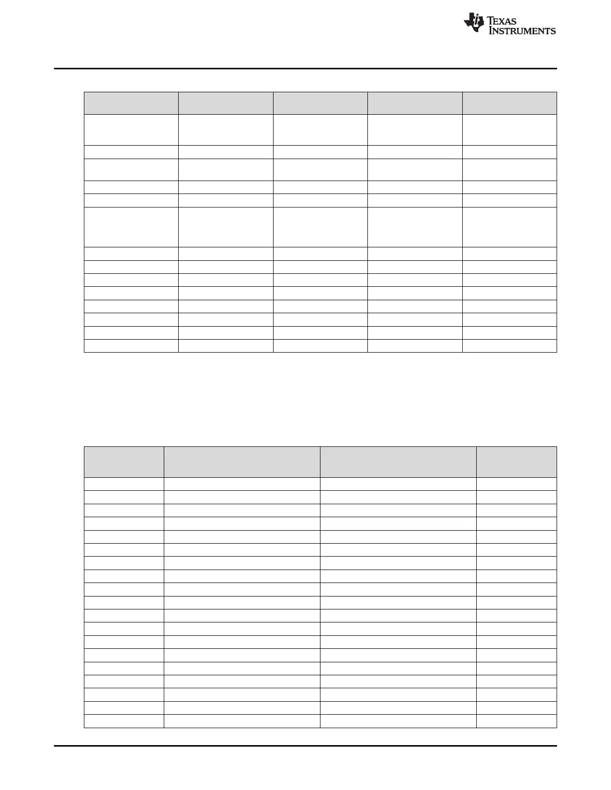
Table 2-6. Exception Types
Exception Type Vector Number Priority
(1)
Vector Address or
Offset
(2)
Activation
– 0 – 0x0000.0000 Stack top is loaded from
the first entry of the
vector table on reset.
Reset 1 –3 (highest) 0x0000.0004 Asynchronous
Nonmaskable Interrupt
(NMI)
2 –2 0x0000.0008 Asynchronous
Hard Fault 3 –1 0x0000.000C –
Memory Management 4 Programmable
(3)
0x0000.0010 Synchronous
Bus Fault 5 Programmable
(3)
0x0000.0014 Synchronous when
precise and
asynchronous when
imprecise
Usage Fault 6 Programmable
(3)
0x0000.0018 Synchronous
- 10 – – Reserved
SVCall 11 Programmable
(3)
0x0000.002C Synchronous
Debug Monitor 12 Programmable
(3)
0x0000.0030 Synchronous
– 13 – – Reserved
PendSV 14 Programmable
(3)
0x0000.0038 Asynchronous
SysTick 15 Programmable
(3)
0x0000.003C Asynchronous
Interrupts 16 and above Programmable
(4)
0x0000.0040 and above Asynchronous
Table 2-7. CC32xx Application Processor Interrupts
Interrupt Number
(Bit in Interrupt
Registers)
Vector Address or Offset Description Type
0 0x0000.0040 GPIO Port 0 (GPIO 0-7)
1 0x0000.0044 GPIO Port A1 (GPIO 8-15)
2 0x0000.0048 GPIO Port A2 (GPIO 16-23)
3 0x0000.004C GPIO Port A3 (GPIO 24-31)
4 0x0000.0050 GPIO port A4 (GPIO 32)
5 0x0000.0054 UART0
6 0x0000.0058 UART1
8 0x0000.0060 I2C
14 0x0000.0078 ADC Channel-0
15 0x0000.007C ADC Channel-1
16 0x0000.0080 ADC Channel-2
17 0x0000.0084 ADC Channel-3
18 0x0000.0088 WDT
19 0x0000.008C 16- or 32-Bit Timer A0A
20 0x0000.0090 16- or 32-Bit Timer A0B
21 0x0000.0094 16- or 32-Bit Timer A1A
22 0x0000.0098 16- or 32-Bit Timer A1B
23 0x0000.009C 16- or 32-Bit Timer A2A
24 0x0000.00A0 16- or 32-Bit Timer A2B