www.ti.com
Register Map
101
SWRU543–January 2019
Submit Documentation Feedback
Copyright © 2019, Texas Instruments Incorporated
Cortex
®
-M4 Peripherals
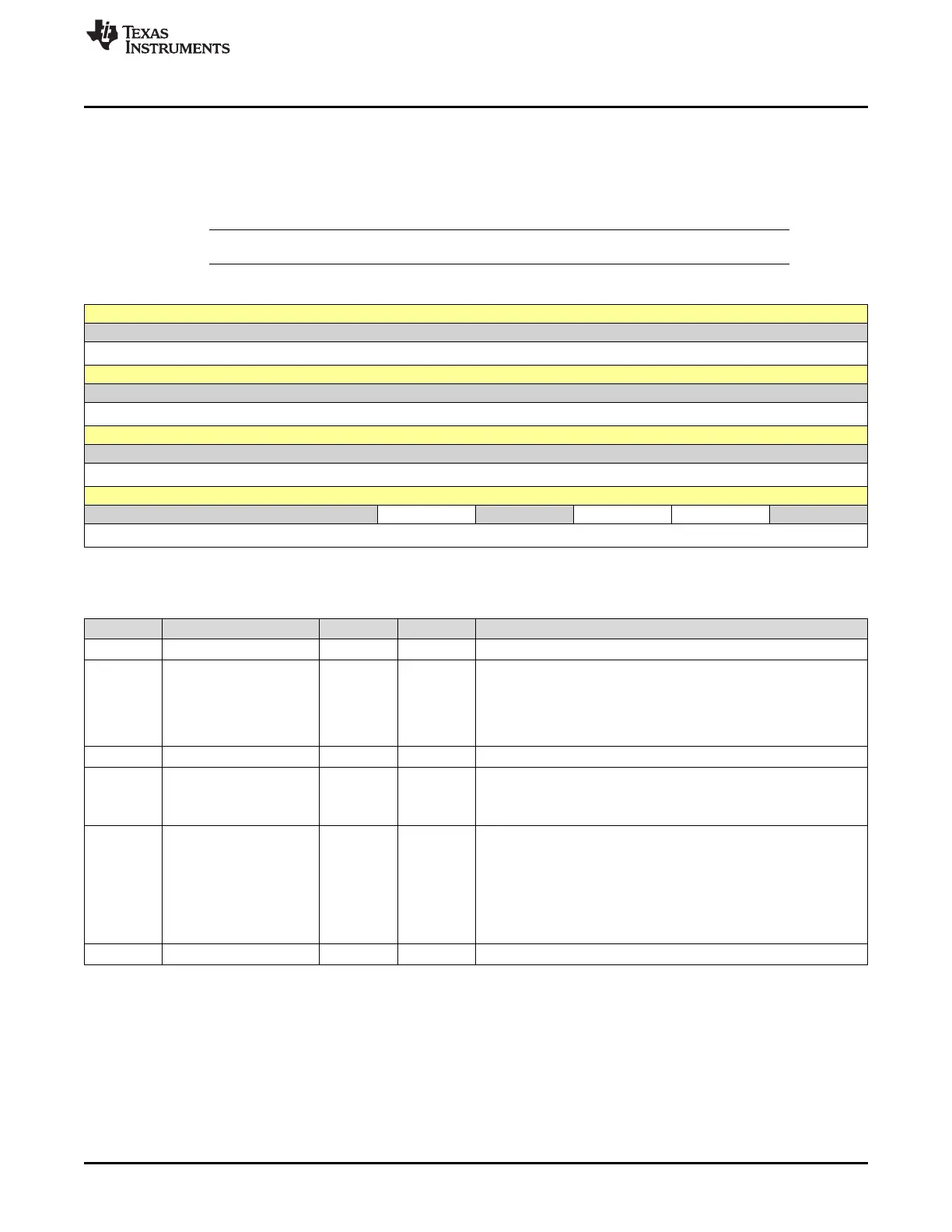
3.3.1.15 SYSCTRL Register (Offset = D10h) [reset = 0h]
SYSCTRL is shown in Figure 3-15 and described in Table 3-18.
Return to Summary Table.
The SYSCTRL register controls features of entry to and exit from low-power state.
NOTE: This register can only be accessed from privileged mode.
Figure 3-15. SYSCTRL Register
31 30 29 28 27 26 25 24
RESERVED
R-0h
23 22 21 20 19 18 17 16
RESERVED
R-0h
15 14 13 12 11 10 9 8
RESERVED
R-0h
7 6 5 4 3 2 1 0
RESERVED SEVONPEND RESERVED SLEEPDEEP SLEEPEXIT RESERVED
R-0h R/W-0h R-0h R/W-0h R/W-0h R-0h
LEGEND: R/W = Read/Write; R = Read only; W1toCl = Write 1 to clear bit; -n = value after reset
Table 3-18. SYSCTRL Register Field Descriptions
Bit Field Type Reset Description
31-5 RESERVED R 0h
4 SEVONPEND R/W 0h
Wake Up on Pending
0h = Only enabled interrupts or events can wake up the processor;
disabled interrupts are excluded.
1h = Enabled events and all interrupts, including disabled interrupts,
can wake up the processor.
3 RESERVED R 0h
2 SLEEPDEEP R/W 0h
Deep Sleep Enable
0h = Use Sleep mode as the low power mode.
1h = Use Deep-sleep mode as the low power mode.
1 SLEEPEXIT R/W 0h
Sleep on ISR Exit
Setting this bit enables an interrupt-driven application to avoid
returning to an empty main application.
0h = When returning from Handler mode to Thread mode, do not
sleep when returning to Thread mode.
1h = When returning from Handler mode to Thread mode, enter
sleep or deep sleep on return from an ISR.
0 RESERVED R 0h