www.ti.com
GPIO Registers
167
SWRU543–January 2019
Submit Documentation Feedback
Copyright © 2019, Texas Instruments Incorporated
General-Purpose Input/Outputs (GPIOs)
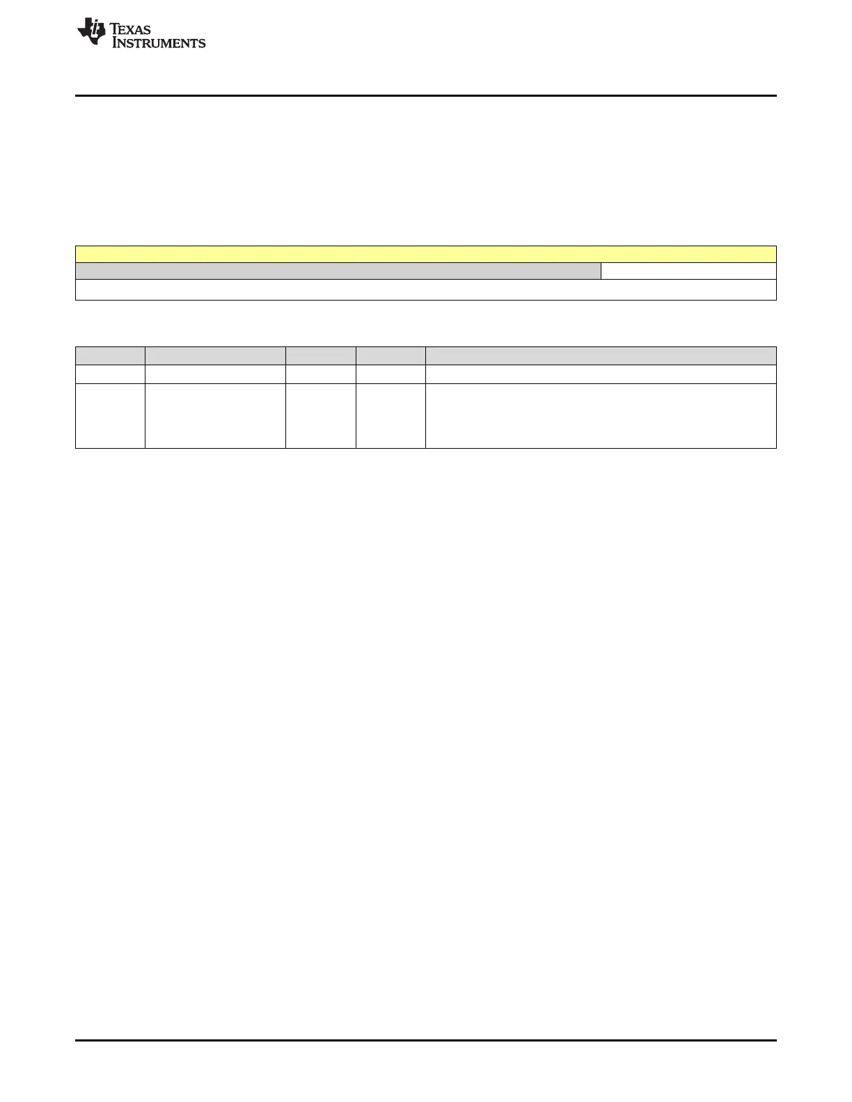
5.5.6 GPIOIM Register (offset = 410h) [reset = 0h]
GPIOIM is shown in Figure 5-9 and described in Table 5-9.
The GPIOIM register is the interrupt mask register. Setting a bit in the GPIOIM register allows interrupts
generated by the corresponding pin to be sent to the interrupt controller on the combined interrupt signal.
Clearing a bit prevents an interrupt on the corresponding pin from being sent to the interrupt controller. All
bits are cleared by a reset.
Figure 5-9. GPIOIM Register
31 30 29 28 27 26 25 24 23 22 21 20 19 18 17 16 15 14 13 12 11 10 9 8 7 6 5 4 3 2 1 0
RESERVED IME
R-0h R/W-0h
Table 5-9. GPIOIM Register Field Descriptions
Bit Field Type Reset Description
31-8 RESERVED R 0h
7-0 IME R/W 0h
GPIO Interrupt Mask Enable
0h = The interrupt from the corresponding pin is masked.
1h = The interrupt from the corresponding pin is sent to the interrupt
controller.