SPI_SCS[n]
SPI_SCLK
SPI_D[1]
SPI_D[0]
Word Word
Word
Functional Description
www.ti.com
272
SWRU543–January 2019
Submit Documentation Feedback
Copyright © 2019, Texas Instruments Incorporated
SPI (Serial Peripheral Interface)
• In 4-pin mode: the MCSPI_MODULCTRL[1] PIN34 bit is set to 0 and the MCSPI_MODULCTRL[0]
SINGLE bit is set to 1, and the SPIEN assertion and deassertion is controlled by software.
8.2.3.3.1 Keep SPIEN Active Mode (Force SPIEN)
Continuous transfers are manually allowed, by keeping the SPIEN signal active for successive SPI words.
Several sequences (configuration – enable – disable of the channel) can be run without deactivating the
SPIEN line.
The keep SPIEN active mode is authorized when:
• The parameters of the transfer are loaded in the configuration register (MCSPI_CHCONF)
• The state of the SPIEN signal is programmable:
– Writing 1 into the FORCE bit of the MCSPI_CHCONF register drives the SPIEN line high when
MCSPI_CHCONF[EPOL] is set to 0, and drives it low when MCSPI_CHCONF[EPOL] is set.
– Writing 0 into the FORCE bit of the MCSPI_CHCONF register drives the SPIEN line low when
MCSPI_CHCONF[EPOL] is set to 0, and drives it high when MCSPI_CHCONF[EPOL] is set.
When the channel is enabled, the SPIEN signal is activated with the programmed polarity. The start of the
transfer depends on the status of the transmitter register and the status of the receiver register.
The status of the serialization completion of each SPI word is given by the EOT bit of the SPI_CHSTAT
register. The EOT bit is set when received data is loaded from the shift register to the receiver register.
A change in the configuration parameters is directly propagated on the SPI. If the SPIEN signal is
activated, the user must ensure that the configuration is changed only between SPI words, to avoid
corrupting the current transfer. SPIEN polarity, the SPICLK phase, and SPICLK polarity must not be
modified when the SPIEN signal is activated. The channel can be disabled and enabled while the SPIEN
signal is activated.
At the end of the last SPI word, the channel must be deactivated (MCSPI_CHCTRL[EN] set to 0) and the
SPIEN can be forced to its inactive state (MCSPI_CHCONF[FORCE]).
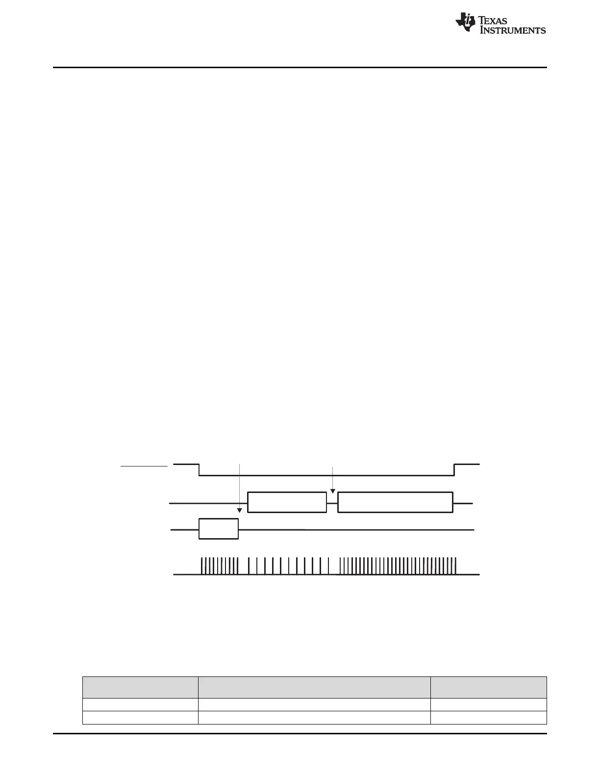
Figure 8-6 shows successive transfers with SPIEN kept active low, with a different configuration for each
SPI word in single data pin interface mode and two data pins interface mode. The arrows indicate when
the channel is disabled before a change in the configuration parameters, and then enabled again.
Figure 8-6. Contiguous Transfers With SPIEN Kept Active (Two Data Pins Interface Mode)
8.2.3.4 Clock Ratio Granularity
The clock division ratio is defined by the MCSPI_CHCONF[CLKD] register, with power of 2 granularity
leading to a clock division in the range of 1 to 32768; in this case, the duty cycle is always 50%.
Table 8-3 provides clock ratio granularity.
Table 8-3. Clock Ratio Granularity
Clock Ratio
F
ratio
CLKSPIO High Time CLKSPIO Low Time
1 T
high
_ref T
low
_ref
Even ≥ 2 T_ref × (F
ratio
/2) T_ref × (F
ratio
/2)

 Loading...


