www.ti.com
Timer Registers
321
SWRU543–January 2019
Submit Documentation Feedback
Copyright © 2019, Texas Instruments Incorporated
General-Purpose Timers
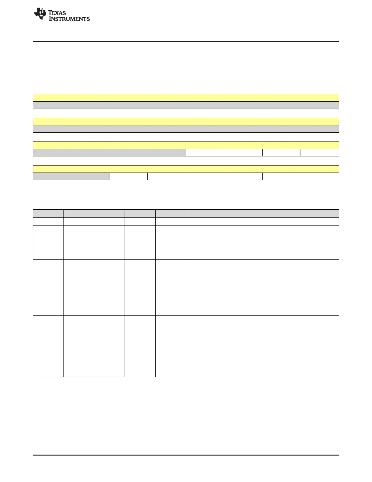
9.5.3 GPTMTBMR Register (offset = 8h) [reset = 0h]
GPTMTBMR is shown in Figure 9-7 and described in Table 9-11.
This register controls the modes for Timer B when it is used individually. When Timer A and Timer B are
concatenated, this register is ignored and GPTMTAMR controls the modes for both Timer A and Timer B.
Figure 9-7. GPTMTBMR Register
31 30 29 28 27 26 25 24
RESERVED
R-0h
23 22 21 20 19 18 17 16
RESERVED
R-0h
15 14 13 12 11 10 9 8
RESERVED TBPLO TBMRSU TBPWMIE TBILD
R-0h R/W-0h R/W-0h R/W-0h R/W-0h
7 6 5 4 3 2 1 0
RESERVED TBMIE TBCDIR TBAMS TBCMR TBMR
R-0h R/W-0h R/W-0h R/W-0h R/W-0h R/W-0h
Table 9-11. GPTMTBMR Register Field Descriptions
Bit Field Type Reset Description
31-12 RESERVED R 0h
11 TBPLO R/W 0h
Timer B PWM Legacy Operation. This bit is only valid in PWM mode.
0h = Legacy operation with CCP pin driven Low when the
GPTMTAILR is reloaded after the timer reaches 0.
1h = CCP is driven High when the GPTMTAILR is reloaded after the
timer reaches 0.
10 TBMRSU R/W 0h
GPTM Timer B Match Register Update. If the timer is disabled
(TBEN is clear) when this bit is set, GPTMTBMATCHR and
GPTMTBPR are updated when the timer is enabled. If the timer is
stalled (TBSTALL is set), GPTMTBMATCHR and GPTMTBPR are
updated according to the configuration of this bit.
0h = Update the GPTMTBMATCHR register and the GPTMTBPR
register, if used, on the next cycle.
1h = Update the GPTMTBMATCHR register and the GPTMTBPR
register, if used, on the next time-out.
9 TBPWMIE R/W 0h
GPTM Timer B PWM Interrupt Enable. This bit enables interrupts in
PWM mode on rising, falling, or both edges of the CCP output as
defined by the TBEVENT field in the GPTMCTL register. In addition,
when this bit is set and a capture event occurs, Timer B
automatically generates triggers to the ADC and DMA if the trigger
capability is enabled, by setting the TBOTE bit in the GPTMCTL
register and the CBEDMAEN bit in the GPTMDMAEV register,
respectively. This bit is only valid in PWM mode.
0h = Capture event interrupt is disabled.
1h = Capture event is enabled.