www.ti.com
Functional Description
207
SWRU543–January 2019
Submit Documentation Feedback
Copyright © 2019, Texas Instruments Incorporated
Inter-Integrated Circuit (I
2
C) Interface
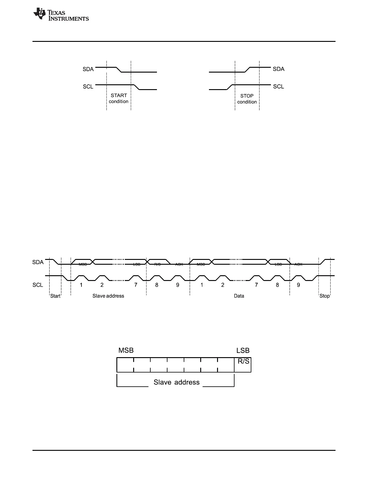
Figure 7-3. START and STOP Conditions
The STOP bit determines if the cycle stops at the end of the data cycle, or continues to a repeated
START condition. To generate a single transmit cycle, the I2C Master Slave Address (I2CMSA) register is
written with the desired address, the R/S bit is cleared, and the Control register is written with ACK=X (0
or 1), STOP=1, START=1, and RUN=1 to perform the operation and stop. When the operation is
completed (or aborted due an error), the interrupt pin becomes active and the data may be read from the
I2C Master Data (I2CMDR) register. When the I2C module operates in master receiver mode, the ACK bit
is normally set, causing the I2C bus controller to transmit an acknowledge automatically after each byte.
This bit must be cleared when the I2C bus controller requires no further data transmission from the slave
transmitter.
7.2.1.2 Data Format With 7-Bit Address
Figure 7-4 shows the format that data transfers follow. After the START condition, a slave address is
transmitted. This address is 7 bits long followed by an eighth bit, which is a data direction bit (R/S bit in
the I2CMSA register). If the R/S bit is clear, the bit indicates a transmit operation (send), and if it is set, the
bit indicates a request for data (receive). A data transfer is always terminated by a STOP condition
generated by the master. However, a master can initiate communications with another device on the bus
by generating a repeated START condition and addressing another slave without first generating a STOP
condition. Various combinations of receive and transmit formats are then possible within a single transfer.
Figure 7-4. Complete Data Transfer With a 7-Bit Address
The first 7 bits of the first byte make up the slave address (see Figure 7-5). The eighth bit determines the
direction of the message. A 0 in the R/S position of the first byte indicates that the master transmits
(sends) data to the selected slave, and a 1 in this position indicates that the master receives data from the
slave.
Figure 7-5. R/S Bit in First Byte
7.2.1.3 Data Validity
The data on the SDA line must be stable during the high period of the clock, and the data line can only
change when SCL is low (see Figure 7-6).