ADC_MODULE Registers
www.ti.com
472
SWRU543–January 2019
Submit Documentation Feedback
Copyright © 2019, Texas Instruments Incorporated
Analog-to-Digital Converter (ADC)
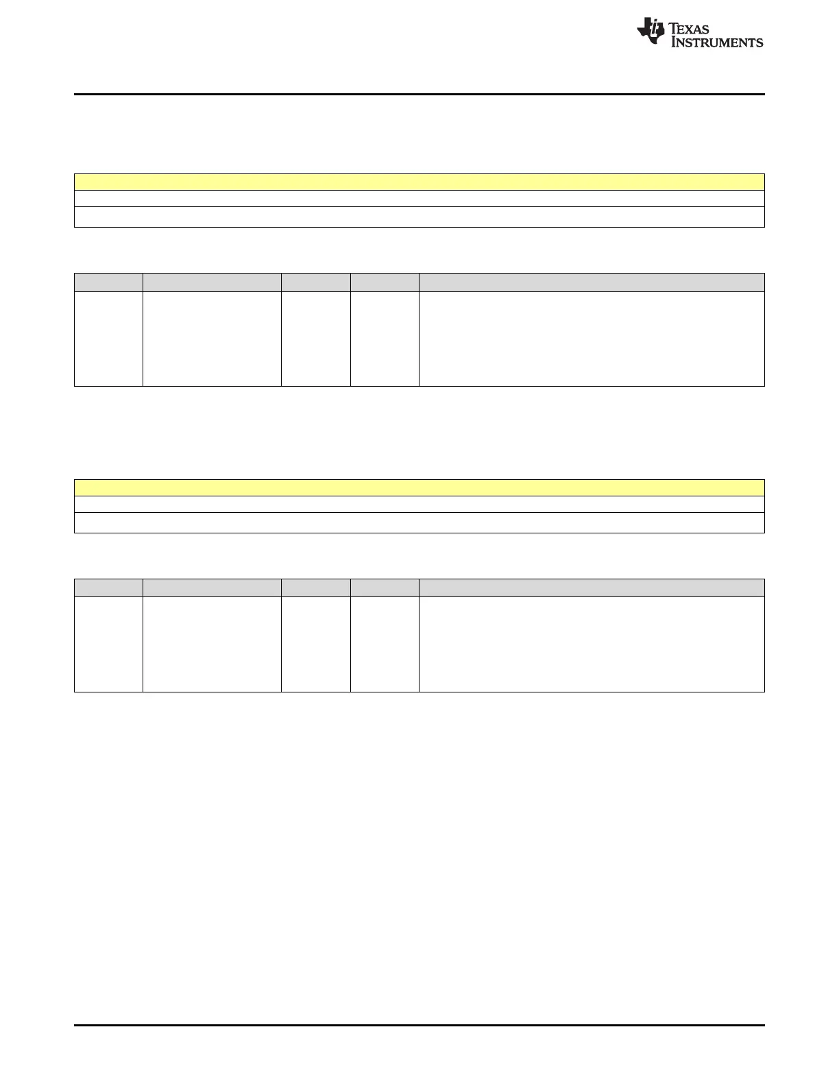
13.4.1.13 CHANNEL0FIFODATA Register (offset = 74h) [reset = 0h]
CHANNEL0FIFODATA is shown in Figure 13-15 and described in Table 13-15.
Figure 13-15. CHANNEL0FIFODATA Register
31 30 29 28 27 26 25 24 23 22 21 20 19 18 17 16 15 14 13 12 11 10 9 8 7 6 5 4 3 2 1 0
FIFO_RD_DATA
R-0h
Table 13-15. CHANNEL0FIFODATA Register Field Descriptions
Bit Field Type Reset Description
31-0 FIFO_RD_DATA R 0h
Read to this register returns ADC data, along with timestamp
information in the following format:
[1:0] : Reserved
[13:2] : ADC sample bits
[30:14]: Timestamp per ADC sample
[31] : Reserved
13.4.1.14 CHANNEL2FIFODATA Register (offset = 7Ch) [reset = 0h]
CHANNEL2FIFODATA is shown in Figure 13-16 and described in Table 13-16.
Figure 13-16. CHANNEL2FIFODATA Register
31 30 29 28 27 26 25 24 23 22 21 20 19 18 17 16 15 14 13 12 11 10 9 8 7 6 5 4 3 2 1 0
FIFO_RD_DATA
R-0h
Table 13-16. CHANNEL2FIFODATA Register Field Descriptions
Bit Field Type Reset Description
31-0 FIFO_RD_DATA R 0h
Read to this register returns ADC data, along with timestamp
information in the following format:
[1:0] : Reserved
[13:2] : ADC sample bits
[30:14]: Timestamp per ADC sample
[31] : Reserved