www.ti.com
I2C Registers
223
SWRU543–January 2019
Submit Documentation Feedback
Copyright © 2019, Texas Instruments Incorporated
Inter-Integrated Circuit (I
2
C) Interface
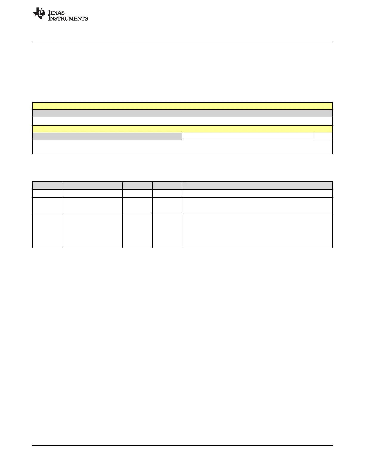
7.3.1 I2CMSA Register (Offset = 0h) [reset = 0h]
I2CMSA is shown in Figure 7-14 and described in Table 7-4.
Return to Summary Table.
This register consists of 8 bits: 7 address bits (A6-A0), and a Receive/Send bit, which determines if the
next operation is a Receive (high), or Transmit (low).
Figure 7-14. I2CMSA Register
31 30 29 28 27 26 25 24 23 22 21 20 19 18 17 16
RESERVED
R-0h
15 14 13 12 11 10 9 8 7 6 5 4 3 2 1 0
RESERVED SA R_S
R-0h R/W-0h R/W-
0h
LEGEND: R/W = Read/Write; R = Read only; W1toCl = Write 1 to clear bit; -n = value after reset
Table 7-4. I2CMSA Register Field Descriptions
Bit Field Type Reset Description
31-8 RESERVED R 0h
7-1 SA R/W 0h
I
2
C Slave Address
This field specifies bits A6 through A0 of the slave address.
0 R_S R/W 0h
Receive/Send
The R/S bit specifies if the next master operation is a Receive (High)
or Transmit (Low).
0h = Transmit
1h = Receive

 Loading...


