www.ti.com
DES Block Diagram
665
SWRU543–January 2019
Submit Documentation Feedback
Copyright © 2019, Texas Instruments Incorporated
Data Encryption Standard Accelerator (DES)
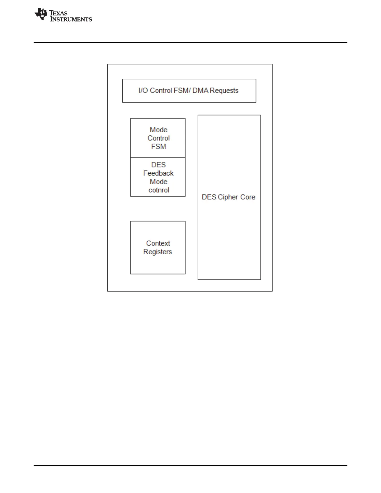
Figure 18-1. DES Block Diagram
18.2.1 µDMA Control
The µDMA and interrupt request logic is controlled by the DES engine. The DES engine can have multiple
µDMA request signals active in parallel.
Three DMA channels are available:
• DMA context in – Request a new context (DES0 Cin)
• DMA data in – Request input data (DES0 Din)
• DMA data out – Request output data read (DES0 Dout)
18.2.2 Interrupt Control
One interrupt for the DES is sent to the interrupt controller. This interrupt is an OR of the enabled interrupt
bits in the DES Interrupt Status (DES_IRQSTATUS) register. These bits are enabled through the DES
Interrupt Enable (DES_IRQENABLE) register. The following events can generate an interrupt bit to be set
in the DES_IRQSTATUS register:
• New context input required
• Data input required
• Data output ready