Flash Registers
www.ti.com
768
SWRU543–January 2019
Submit Documentation Feedback
Copyright © 2019, Texas Instruments Incorporated
On-Chip Parallel Flash
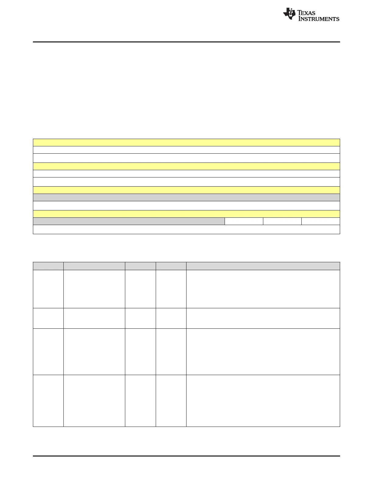
21.5.3 FMC Register (Offset = 8h) [reset = 0h]
FMC is shown in Figure 21-3 and described in Table 21-4.
Return to Summary Table.
When this register is written, the flash memory controller initiates the appropriate access cycle for the
location specified by the Flash Memory Address (FMA) register. If the access is a write access, the data in
the Flash Memory Data (FMD) register is written to the specified address.
This register must be the final register written, and initiates the memory operation. The 4 control bits in the
lower byte of this register are used to initiate memory operations.
Do not set multiple control bits, because the results of such an operation are unpredictable.
Figure 21-3. FMC Register
31 30 29 28 27 26 25 24
WRKEY
WO-0h
23 22 21 20 19 18 17 16
WRKEY
WO-0h
15 14 13 12 11 10 9 8
RESERVED
R-0h
7 6 5 4 3 2 1 0
RESERVED MERASE ERASE WRITE
R-0h R/W-0h R/W-0h R/W-0h
LEGEND: R/W = Read/Write; R = Read only; W1toCl = Write 1 to clear bit; -n = value after reset
Table 21-4. FMC Register Field Descriptions
Bit Field Type Reset Description
31-16 WRKEY WO 0h
Flash Memory Write Key
This field contains a write key, which is used to minimize the
incidence of accidental flash memory writes. The value 0xA442 must
be written into this field for a flash memory write to occur. Writes to
the FMC register without this WRKEY value are ignored. A read of
this field returns the value 0.
15-3 RESERVED R 0h
Software should not rely on the value of a reserved bit. To provide
compatibility with future products, the value of a reserved bit should
be preserved across a read-modify-write operation.
2 MERASE R/W 0h
Mass Erase Flash Memory
This bit is used to mass-erase the flash main memory and to monitor
the progress of that process.
0h = A write of 0 has no effect on the state of this bit. When read, 0
indicates that the previous mass-erase access is complete.
1h = Set this bit to erase the flash main memory. When read, 1
indicates that the previous mass-erase access is not complete.
1 ERASE R/W 0h
Erase a Page of Flash Memory
This bit is used to erase a page of flash memory and to monitor the
progress of that process.
0h = A write of 0 has no effect on the state of this bit. When read, 0
indicates that the previous page-erase access is complete.
1h = Set this bit to erase the flash memory page specified by the
contents of the FMA register. When read, 1 indicates that the
previous page-erase access is not complete.