Programming Model
www.ti.com
404
SWRU543–January 2019
Submit Documentation Feedback
Copyright © 2019, Texas Instruments Incorporated
Inter-Integrated Sound (I2S) Multichannel Audio Serial Port
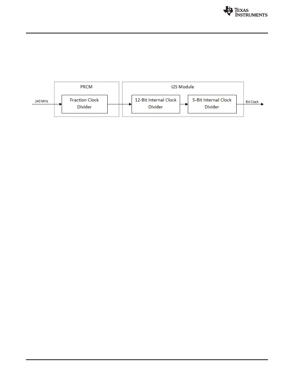
This divider can be configured using the PRCMI2SClockFreqSet(unsigned long ulI2CClkFreq) API from
the PRCM module driver.
The module also has two internal dividers supporting a wide range of bit clock frequency. Figure 12-3 is a
block diagram that shows the logical clock path.
Figure 12-3. Logical Clock Path
The user resets the module to return the internal registers to their default state by calling the PRCM reset
API with the appropriate parameters.
12.3.2 I2S Data Port Interface
The I2S module has two data interfaces: CPU port and DMA port. Either port can be used to feed transmit
data into the I2S transmit buffer, or read received data from the receive buffer.
CPU Port: This port exposes the I2S buffers as 32-bit registers with one register per serializer (or data
line), and can be written or read using the following APIs:
• I2SDataPutNonBlocking(unsigned long ulBase, unsigned long ulDataLine, long ulData)
• I2SDataPut(unsigned long ulBase, unsigned long ulDataLine, long ulData)
• I2SDataGetNonBlocking(unsigned long ulBase, unsigned long ulDataLine, long &ulData)
• I2SDataGet(unsigned long ulBase, unsigned long ulDataLine, long &ulData)
DMA Port: This port exposes the I2S buffers as two 32-bit registers, one each for transmit and receive.
The transmit port services each serializer configured as a transmitter in a cyclic order, if multiple
serializers are configured as a transmitter.
Similarly, the receive port services each serializer configured as a receiver in a cyclic order if multiple
serializers are configured as a transmitter.
The ports can be assessed using the following macros:
• I2S_TX_DMA_PORT 0x4401E200
• I2S_RX_DMA_PORT 0x4401E280
12.3.3 Initialization and Configuration
I2S on the CC32xx device acts as master providing frame-sync and bit clock to the slave, and can operate
in two modes: transmit-only mode and synchronous transmit–receive mode.
In transmit-only mode, the device is only configured to transmit data. In synchronous transmit–receive
mode, the device is configured to transmit and receive in a synchronous manner. In both cases the data
transmitted and received is in sync with the frame-sync and bit clock signals generated internally by the
I2S module.
This section shows a module initialization and configuration example for each mode supported to transmit
and receive 16-bit, 44.1-kHz audio.
1. Computing bit clock from sampling frequency and bits/sample:
BitClock = (Sampling_Frequency * 2 * bits/sample)
BitClock = (44100 * 2 * 16) = 1411200 Hz
2. Basic initialization
a. Enable the I2S module clock by invoking