Camera Registers
www.ti.com
506
SWRU543–January 2019
Submit Documentation Feedback
Copyright © 2019, Texas Instruments Incorporated
Parallel Camera Interface Module
14.6.7 CC_CTRL_XCLK Register (Offset = 48h) [reset = 0h]
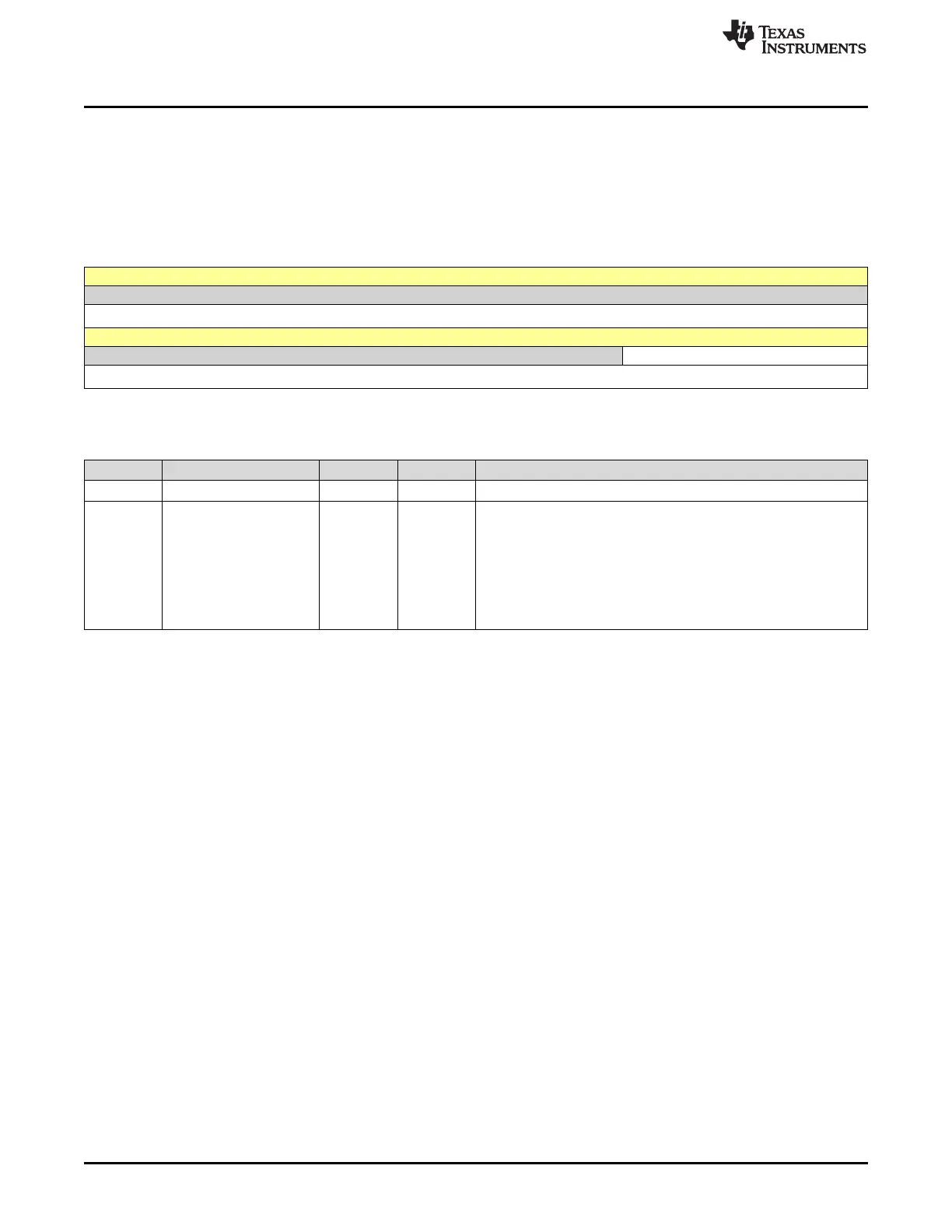
CC_CTRL_XCLK is shown in Figure 14-15 and described in Table 14-10.
Return to Summary Table.
This register controls the value of the clock divisor used to generate the external clock (parallel mode).
Refer to Table 14-2 for details about the ratio of XCLK frequency.
Figure 14-15. CC_CTRL_XCLK Register
31 30 29 28 27 26 25 24 23 22 21 20 19 18 17 16
RESERVED
R/W-0h
15 14 13 12 11 10 9 8 7 6 5 4 3 2 1 0
RESERVED XCLK_DIV
R/W-0h R/W-0h
LEGEND: R/W = Read/Write; R = Read only; W1toCl = Write 1 to clear bit; -n = value after reset
Table 14-10. CC_CTRL_XCLK Register Field Descriptions
Bit Field Type Reset Description
31-5 RESERVED R/W 0h
4-0 XCLK_DIV R/W 0h
Sets the clock divisor value for CAM_XCLK generation.
Based on CAM_MCLK (value of CAM_MCLK IS 96 MHz).
Divider not enabled
00000000h = CAM_XCLK Stable low level
00000001h = CAM_XCLK Stable high level
from 2 to 30 = CAM_XCLK = CAM_MCLK / XCLK DIV
00011111h = Bypass - CAM_XCLK = CAM_MCLK





 To Next Page