Register Description
www.ti.com
132
SWRU543–January 2019
Submit Documentation Feedback
Copyright © 2019, Texas Instruments Incorporated
Direct Memory Access (DMA)
4.3.4 DMA_(OFFSET_FROM_DMA_BASE_ADDRESS) Registers
Section 4.3.4 lists the memory-mapped registers for the
DMA_(OFFSET_FROM_DMA_BASE_ADDRESS). All register offset addresses not listed in Table 4-10
should be considered as reserved locations and the register contents should not be modified.
Table below lists the DMA channel control structures and registers. The channel control structure shows
the layout of one entry in the channel control table. The channel control table is located in system
memory, and the location is determined by the application, thus, the base address is n/a (not applicable)
and noted as so above the register descriptions. In the table below, the offset for the channel control
structures is the offset from the entry in the channel control table. See Channel Configuration table for
description of how the entries in the channel control table are located in memory. The DMA register
addresses are given as a hexadecimal increment, relative to the DMA base address of 0x400F.F000. Note
that the DMA module clock must be enabled before the registers can be programmed. There must be a
delay of 3 system clocks after the DMA module clock is enabled before any DMA module registers are
accessed.
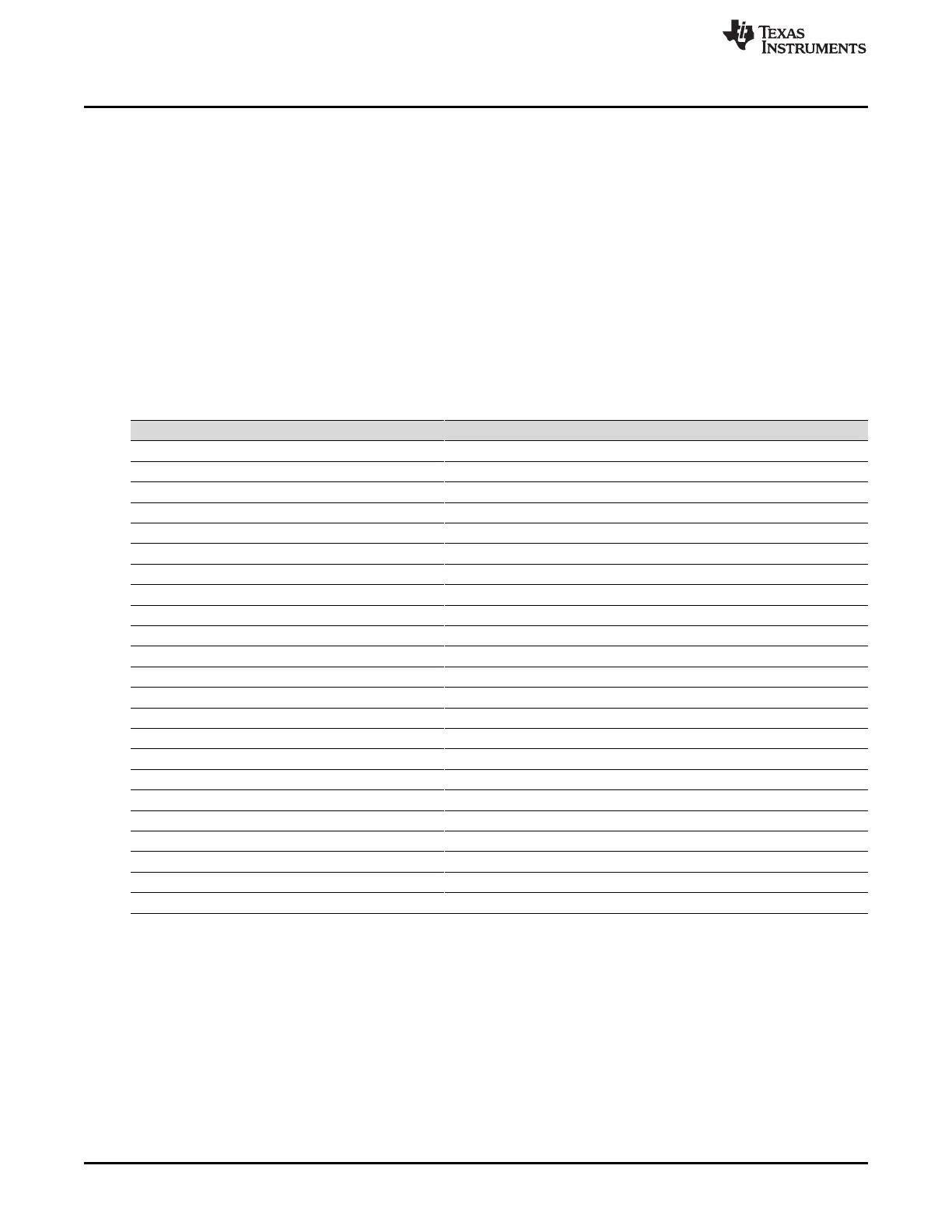
Table 4-10. DMA_(OFFSET_FROM_DMA_BASE_ADDRESS) Registers
Offset Acronym Register Name Section
0h DMA_STAT DMA_STAT Section 4.3.4.1
4h DMA_CFG DMA Configuration Section 4.3.4.2
8h DMA_CTLBASE DMA Channel Control Base Pointer Section 4.3.4.3
Ch DMA_ALTBASE DMA Alternate Channel Control Base Pointer Section 4.3.4.4
10h DMA_WAITSTAT DMA Channel Wait-on Request Status Section 4.3.4.5
14h DMA_SWREQ DMA Channel Software Request Section 4.3.4.6
18h DMA_USEBURSTSET DMA Channel Useburst Set Section 4.3.4.7
1Ch DMA_USEBURSTCLR DMA Channel Useburst Clear Section 4.3.4.8
20h DMA_REQMASKSET DMA Channel Request Mask Set Section 4.3.4.9
24h DMA_REQMASKCLR DMA Channel Request Mask Clear Section 4.3.4.10
28h DMA_ENASET DMA Channel Enable Set Section 4.3.4.11
2Ch DMA_ENACLR DMA Channel Enable Clear Section 4.3.4.12
30h DMA_ALTSET DMA Channel Primary Alternate Set Section 4.3.4.13
34h DMA_ALTCLR DMA Channel Primary Alternate Clear Section 4.3.4.14
38h DMA_PRIOSET DMA Channel Priority Set Section 4.3.4.15
3Ch DMA_PRIOCLR DMA Channel Priority Clear Section 4.3.4.16
4Ch DMA_ERRCLR DMA Bus Error Clear Section 4.3.4.17
500h DMA_CHASGN DMA Channel Assignment Section 4.3.4.18
510h DMA_CHMAP0 DMA Channel Map Select 0 Section 4.3.4.19
514h DMA_CHMAP1 DMA Channel Map Select 1 Section 4.3.4.20
518h DMA_CHMAP2 DMA Channel Map Select 2 Section 4.3.4.21
51Ch DMA_CHMAP3 DMA Channel Map Select 3 Section 4.3.4.22
FB0h DMA_PV DMA Peripheral Version Section 4.3.4.23





 To Next Page